Wednesday, September 28, 2022

Universal M25-XP Alternator Support Arm Failure - Again

Universal M25-XP Alternator Support Arm Failure - Again

Twice in the past 7 years, I have purchased a pair of OEM Support arms for our Alternator on our Universal M25-XP Diesel engine, I have one left and have no reason to think that it will last as long as the others, in other words, failure is imminent. 

When they fail, they break near the top attachment slot and, luckily, it has not been a disaster. When they break, the arm falls down about an 1/8" of an inch, not much, but enough for the arm to rub against the Coolant piping and the potential rupture of the pipe and consequential loss of engine coolant. That could be a disaster.

I went to a local machine shop and described the problem and taking the last remaining arm with me to use as a template.

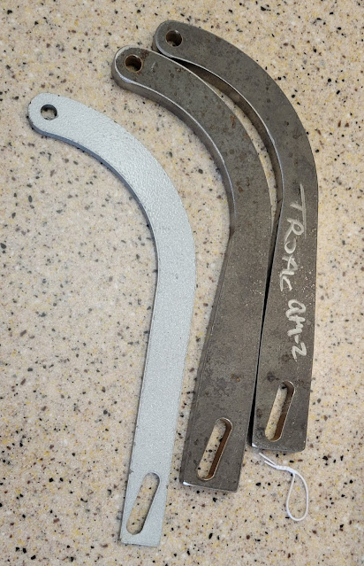
My request was to double the thickness of the arm from 3/16" to 3/8" and to expand the width at the slotted end by a 1/4" They did a great job.

The Gray arm is the original


The Original is laying on top of the new arm

Just spent a few minutes cleaning the surfaces with a nylon sanding pad, clean with Acetone and  then a couple of coats of spray High Heat Resistant Rust-oleum paint followed by a couple of coats of Rust-Oleum Metallic paint ( just happened to have some of that on the shelf) .  

L-to-R Original, Primed, Finished

Should be able to get down to the boat on Friday to install one, the second piece will get wrapped with clingfilm and stored on the boat with all of the other engine spares.

They were not cheap! The new arms cost $150 for one and $200 for two, but they now have a Drawing of them incase anyone wants one or two.

If you want one ( or two) reach out to them. The invoice number is 25326 for reference.
Tropic Marine Products
217 SW 29th Street
Fort Lauderdale FL 333015
Phone: 954-779-7038

I'm not getting any compensation for promoting these, but I know that so many Universal M25-XP owners have had similar issues.  

See you on the water.

Wednesday, September 14, 2022

Installing a Balmar MAX Charge MC-618-H External Alternator Regulator

Installing a Balmar MAX Charge MC-618-H Regulator


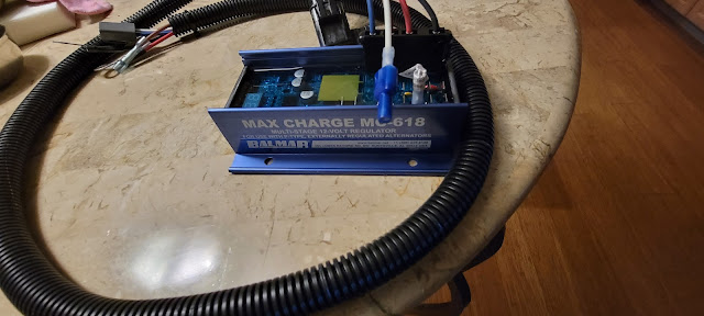
Our existing External Regulator is a backup unit from when the Zantrex Power Management System was installed, now replaced with our Victron Power Management System. The old external regulator does not have the features to protect our Balmar 6 series 100A Alternator nor does it consider the battery temperature nor the Battery Voltage. The Balmar MAX MC-618 does ( The H indicated that it is supplied with an electrical harness.)

I purchased the regulator from PKYS online and was surprised that it's cost was competitive with Amazon and it's delivery was at least as good, it arrived early.  When it arrived, I thought I had the wrong item. I sent an email to PKYS explaining that they had sent the wrong item.

But!!! As you can see from the picture above, it's identified as a MAX Charge MC-618 not as an MC-618-H, I found that the label on the underside of the regulator shows it's a MC-618-H I and sent a follow up email to PKYS apologizing for my mistake.


I read through the manual again and realized that I didn't order the two Temperature Sensors, Duh! I placed another order for them. After placing the order, I called PKYS just to make sure they didn't react to my first email regarding the wrong item. They actually picked up the phone and responded to my query. Very helpful. The order for the two temp sensors arrived a day earlier than expected ( ordered Monday arrived Wednesday )

As I mentioned, I read the manual. It's online but I downloaded it and stored it in my 'Manuals' folder for future use. I'm going to print it to keep  on board with my other manuals, just in case I'm ever out at sea and no net connection.

Ok, Onto the Installation.

My plan is to keep the existing dumb regulator as a backup, it works, just not very efficiently.

Here's the rough process:

  • Install the Regulator ( 4 screws ) adjacent to the old regulator.
  • Run the wiring harness into the engine area and connect to the Alternator
  • Run the Alternator Temperature Sensor wiring to one of the Alternator Body Nut-n-Bolt
  • Run the Battery Temperature Sensor beneath the engine area Port side into the Battery bay just forward of the Galley forward bulkhead ( about midships )
  • Run a cable for the Battery Voltage Sense wire alongside the Battery Temperature sensor cable.
Sounds pretty straight forward. Next it's time to program the regulator. I'll need to turn the engine ignition on for that. But first I have to do a bit of work on the Alternator housing.


On our 100nm trip to Lake Worth and back over the Labor day weekend, the engine kept showing intermittent RPM although it sounded great and was running very steady. 

Turns out it was the Drive belt lose again!  I went to Broward Bolt and got a few of these Nord-Lock washers used to keep Turbo Units on cars & trucks from shaking lose. 

I need to adjust the belt tension and lock the bolts in place with these washers.

FYI, I make a point of going to Broward Bolt as soon as I need any type of bolt, nut or washer! 

1560 N Powerline Rd, Pompano Beach, FL 33069

The staff are awesome, they have never been out of stock for anything that I needed and have always been really helpful. Must admit, when I first went there a few years ago, I was expecting they would be expensive but happily surprised that their prices are very reasonable. They are not sponsoring me at all, I just feel the need to promote really good customer service. Give them a call next time you need Nuts, Bolts or Washers ( and drill bits, hole saws and two part epoxy mixes - the type in Tubes like Caulk ) (954) 960-1740


Here's the wiring diagram for this project.


OK, we're headed down to the boat in the morning, I'll try to take a bunch of pics of the install and Alternator Tensioning.


Tuesday, August 16, 2022

Completing the VHF Antenna Cable install

 Back up the mast to complete the install of the VHF Antenna and gWind Transducer cables.


Now that the VHF has tested out ok and the gWind transducer is providing wind data to our Navigation System, it's time to complete the work on the Masthead.

So it was back up the mast today. No rain expected ( ok, none after 10am) but plenty of Sunshine. Steffi Shiffer came down to the boat to collect the left over material from the chair cushions and backs that I made for her last week. Peggy & Steffi were chin wagging while I prepped the gear for climbing the mast.
Today's tools included the Heat Gun, 100' Extension Cable, Pliers, Snips and Knife plus the Safety Harness and Bosuns Chair along with the two ATN Ascenders. Materials required were Heat Shrink tubing, Dielectric Grease, Butyl Tape, and Zip ties. Add a bottle of water for refreshment. I was also going to replace the blocks for the Lazy Jack system and apply some Rescue Tape to the end of the starboard side of the spreader, I got the port side of the spreader done last week.

It's always a struggle to don the Safety Harness, my solution is to sort it out while it's laying on the dock and then pick it up with one of the shoulder straps in each hand and lift it up over one arm and then pass the other arm under the second shoulder strap. Then connect the two parts of the chest straps and finally reach down and pull each of the leg straps up between my legs and connect them to the two side clips.

With all of the tools and materials sitting on the top of the inverted dinghy on the foredeck, I sit in the bosun's chair and strap into that. I use a additional strap to pull my butt into the back of the chair so that the chair does not slip bac when I stand in the leg straps stirrups. 

Next I attach the two ascenders to the Halyard that I have tensioned ready for climbing, I'll have to get better at tensioning that line. When I put my weight on the ascenders, it stretches and thus loosens.

Now fully dressed ( where are the pics Peggy? ) I load up the tool bags on each side of the bosun's chair. Clipping the Main Halyard to the end of the Safety Harness shock cord, Peggy takes up the slack and I hook into the Ascenders, one attaches to the Bosun's Chair the other to the Leg Straps with my feet in the Stirrups. Finally ready to climb. 

Peggy takes up the slack as I ascend the mast.

When I get to the Spreaders, Peggy secures the safety line and I reach out to the tip of the spreader. Ok, I can reach it! All I need is my knife and the Rescue tape they are in my tool bags. I lean out with the tape in hand and quickly wraps the tip of the spreader with the tape, cut it with the knife and stretch and wrap the last few inches of the tape around the spreader. Job 1 Done.

Ok, moving up. Peggy takes up the slack and I climb up a couple of feet to the Lazy Jack blocks on each side of the mast just above the Spreaders. The Starboard block had failed, the 'plastic' sides had cracked and allow the Line to ride up over the sheave and then jamb between the sheave and the metal sides of the block. I quickly installed the new all Stainless steel sided blocks, running the new lazy jack lines would be a job for on the way down.

Again, Moving up. Peggy takes up the slack as I climb the remaining distance to the top of our mast which is about 51 feet above the water line. Took a break halfway there for a refreshing drink of water. 

Once at the top, I got to work. First was to put dielectric grease on the VHF Antenna Connection to the Antenna Cable. I slipped a piece of Heat Shrink over and past the end of the cable, applied the grease to the thread of the Antenna Connection, completed the connection and tightened it using the pliers, then slid the Heat Shrink over the connecting ferrule. Calling down to Peggy, she attached the power cord and the Heat Gun up to via the Messenger line ( Spinnaker Halyard) and I sealed the Antenna Connection using the heat gun, that should keep it in good condition for a few years.  

Next, I added strain relief to the gWind Transducer cable with several Zip Ties. I should have put an extra piece of heat shrink over the VHF Antenna cable before the piece I had put on to seal the antenna to cable connection, had I done so, it would have been easy to run it down the cable just to the point beyond where the Antenna Cable passes through the hole in the Masthead. I didn't ! So I sliced a piece of heat shrink lengthwise and wrapped around the cable, sliding it down into the hole where the cable passed into the masthead. I secured it with a couple of zip ties and then applied some heat with the heat gun, just enough to melt the glue. 

Last job was to seal the holes around all of the cables where they pass into the Masthead. I rolled up some Butyl tape into a thin rope and used  that to seal the holes around the cables. 

All done, just needed to take some pics.


The old wind transducer base is still on the mast head. It's through bolted, so no way to get it off without having the nut end drop inside the mast and it would be just my luck that that nut would jamb into some line and cause a problem.

Time to go back down to the Lazy Jack Blocks.

Peggy eased the Safety line as I climbed down using the Ascenders until I was level with the blocks.

Using the messenger line, Peggy passed up a piece of line that was precut ( used as a messenger line when I pulled the old wires out of the top of the mast) and the end of the line for the 2nd lazy jack.

Turns out the old messenger line was too short, so I had Peggy tie a knot in the other line from the drum of line that was on the deck, then I pulled up that line until I got to the knot. Cutting the line below the knot, I pulled up on the other line as Peggy unwound more off o the drum. With enough line fed through the new blocks, I had Peggy tie another knot in the line by the drum.


All done, time to climb down the mast. The temp (according to my cell phone ) was over 100ยบ F up at the masthead, it felt like it. I was ready for a break.

We had lunch in the Air Conditioning of the Cabin. Back to it, tide up all of the tools and the gear and lines.

Tools - Good
Gear - Good
The Lazy jack lines - Good - well half were good, the Stbd side lines were secure but  the port side lines decided to run through the blocks - how nice and easy it ran! 

That means I have to go up the mast again on Friday to fix the lazy jack lines.   Grrr. At least it will keep me fit.

Getting better at climbing the mast, it went a whole lot easier today.  Both new Lazy Jack lines are not run through the new blocks on the mast.

I can cross this job off the list. The Service history log is updated.

There are no projects that would stop us going sailing, plenty of projects still on the list, but none that impact our sailing options. So we're planning.

See you on the water.

Paul

Saturday, August 6, 2022

Final Part of the Victron Power Management System Install

Mounting the Victron GX 4G LTE Modem & GPS Antenna

The Victron system installation has been working great for nearly a month now. It communicates with the Victron VRM on the Internet via a GX 4G LTE Modem. That has a small Stick Antenna and I was not happy with having that in the open down in the cabin, too great a risk that someone might nudge it and thus disconnect us from the net or worse, damage the modem. I had a Remote Antenna from a Wilson Cellular Extender that never worked well on our previous boat so I replaced the Stick Antenna with the Extension Antenna - Worked great when I left it just sitting on the shelf above the Nav Table until verified it worked ok.
Similarly, the GPS puck which connects to the 4G LTE Modem was just sitting on a shelf above the Nav Table,

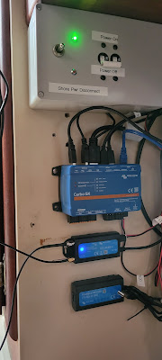
The Pic shows the two cables from the GX 4G LET Modem (that's the unit with the blue light) 

Today I relocated the Antenna and GPS Puck to their permanent location. 

All I have left to do is run the wires from them to the LTE Modem. That should tidy up the installation significantly. I also replaced the 5m Network Cable from the Cerbo GX to the Victron Mk3 - USB interface with a .9m cable and, again, vastly improves the cable management.


Just to brag a bit, here's a screen shot of my Laptop at home showing part of the VRM data display.


Next job on the boat is to loom the new VHF Cable and the new gWind Transducer cable into the existing looms to secure them in place.  We're close to taking the boat out for an overnight really soon.

So, "See you on the Water" is not an empty promise. 


Monday, August 1, 2022

Replacing the Masthead Antenna Cable - a Friend Indeed.

 Another trip up the mast, 3rd time in a couple of weeks.

Before getting ready to climb the mast, I had secured the lower ends of the two wires we were replacing with Heat Shrink tubing to individual messenger lines - 1/4" Braided Poly line. The tubing hot melt glue did a good job of join the tubing to the wires and the line.


Getting better at climbing the mast, the new Ascenders from ATN work really well, especially when they are attached at the correct length from each other to suit my body length.

My Dock Neighbor, Doug, took a bunch of pics while he was lazing in his Pool and I was the local entertainment.  Peggy was too busy managing the Belay Line ( safety line ) at the winch in the Cockpit.

I was wearing my Safety Harness, Bosun's Chair, tool pouches. Long sleeved top with Hoodie ( something around SPF 50 ) hard soled shoes. In my tool bags were a Cordless Drill, a bunch of lines ( for use as messengers, safety lanyards to prevent tools taking a dive, etc.) Pliers, Needle nose Pliers, Drill set, Self Amalgamating Rescue Tape, Bottle of Water, etc. etc. I probably was pulling up about 180lbs when climbing. 

The good news is that it is so much easier now that I have the process down. Even Peggy noted that I reached the top a lot quicker this time and I spent much less time getting kitted out before starting the climb.


Once at the top I got to work. Step one was to remove the Silicone caulk that was covering the VHF Antenna Cable, the old Wind Transducer cable ( original from when we purchased the boat but unused as the old transducer was broken ) .


With the Silicone out of the way, next it was time to pull the old wires out of the top of the mast. The VHF antenna cable had about a foot of wire above the mast head. The Old Transducer wire only had about 2" of wire sticking out of the mast head. I tied a line to that wire, then I called Peggy on my cell phone and she started to feed the Transducer wire up through the hole at the base of the mast.

Gladly, the wires pulled up out of the top of the mast quite easily, I was able to pull about a foot of wire with a singe reach. As the wire came out, I let it dangle down from the mast. With the top of the wire secured with that line I tied earlier, the weight on the line was only about 1/2 the total weight. Once a wire was all the way out and the Messenger secured to the mast head, I dropped the wire down to the deck. To prevent freaking out Peggy, I  advised her that I was doing that so that the sound of something clattering down onto the cabin top.


Next task was to make a new hole in the Mast head large enough to pass the new VHF Antenna Cable. The cable is 3/8" dia, so I drilled a 1/2" hole close to the original hole. Then I drilled between the two holes and cut out the sliver of metal (Aluminum) between them so that I could move the VHF Antenna Messenger line between the, small, original, hole and the new 1/2" hole.

Using the cell phone again, I called to Peggy to pass up the Antenna Cable and the Transducer cable. I had not wanted to carry them with me when I climbed the mast, it was another 15lbs - the Antenna cable is 90' long and the transducer cable is 82' long.

Peggy attached the rolls of wire to a spare halyard and we pulled them up to my work station 52' above the water.

I had trimmed off the outer sheath of the VHF cable before climbing the mast. I used the Rescue tape to join the messenger line to the VHF Cable and had Peggy start to pull the messenger line out of the hole at the base of the mast as I feed the Cable down into the new hole in the mast head.  The first 30' went well, but it more difficult for Peggy to pull it out of the mast base. 


I called my Son, he lives nearby, and left a message asking if he could call me back when he got the message as I needed some help on the boat. Next I called a sailing buddy, Atilio. He has the same model boat as Eximius and he lives just a few blocks from the Boat. Without hesitation, Atilio dropped everything  ( it was Saturday ) and drove down to help.

With Atilio ( Hero ) down in  the Cabin, he was able to pull the messenger line as I continued to feed the cable into the hole atop the mast head. Eventually, with a bit of push and pull at both ends, we got the connection from the Messenger line and the VHF cable out of the base of the mast. That left another 40' of cable, I could only imagine the sight of the wires & messenger lines down in the cabin.

Once the VHF cable was fed down the mast head with about 18" to go, we stopped and I attached the connector on the end of the cable to the VHF Antenna. One job down!


Atilio was ok to stay a while longer so we repeated that process with the new Wind Transducer cable. It was a lot easier, probably because it was a lot more flexible. There were a couple of places where it required a significant pull on the Messenger line, I'm guessing that it was as the messenger/wire joint was passing the rivets that hold the conduit through which the cable pass down the inside of the mast to stop them getting chafed by the mast internal halyards. So I have a slight concern that the wire it ok, we'll find out when we go back to the boat on Wednesday/Thursday (weather dependent) 


Atilio passed me the new Wind Transducer and I pulled that up. A couple of minutes later, it was installed and the Transducer cable was connected. 

I secured the cable to the Transducer support tube with a piece of line. I'll add a few Zip ties later. 

I'm really pleased with progress this far.  I had anticipated several possible issues, like: Not being able to pull the lines up through the mast head, The messenger lines separating from their cables, cables getting stuck inside the mast and a whole lot of other issues including what would happen if I had a medical issue while up the mast. That last item I just cast off. Anyone could have an issue while climbing, at the top or while descending. Rig could fail. How about the sudden urge to go to the bathroom! That's the scariest thought. 

Fortunately, none of those fears came to fruition. I'm lucky in that I don't worry about those things when I'm on task. My usual practice is 'Just Deal with It', a practice that has served me well during that past 73 years.


At that point, everything was done at the mast head until I have done the testing of both the VHF Radio and the Wind Transducer data at the Nav station at the helm.

Peggy & Atilio moved out to the Cockpit and prepared to lower me rather then me having to climb down the mast.

As I descended, I caught my feet on the aft side of the Mast Spreaders and had to perform a bit of gymnastics. Further down a bit further, my right leg got snagged on a line and time for more gymnastics. Note to self, next time have someone check as I'm descending that I'm not going to snag a line. It's a lot easier to avoid a snag than it is to practice Aerial acrobatics to get out of the snag.

Back down at the deck, I was sat on the dinghy and it was easy to get out of my climbing gear. Once free, I went aft to thank Atilio and we all went down into the cabin to see how it tuned out. 

As we talked about boat projects ( there's always more projects ) I wound up the cables  and tidied the boat.  After a snack and more fluids, we were ready to quit for the day. Atilio, our Hero, saved me from having to climb down the mast and back up later to get this far. His help was a game changer! Thanks Atilio!

So, Thanks to Atilio for helping out today, and thanks to Doug  and taking the pictures.

We tidied up the boat, secured all of the lines and headed home - calling Annies Pizza en-route to order a Calzone. We stopped there and picked up our lunch.

So, the status of the project:
The VHF Antenna Cable is connected to the VHF Antenna at the mast head.
The New Wind Transducer is installed at the Mast head and the Data / power cable is connected.
Both cables are wound up in the cabin. 

The VHF cable has to be loomed towards the AIS Antenna Splitter and have a new Connection made up to the end of the cable when the length is known.
I'll leave some slack near the mast base so that I can cut the cable when I have to pull the mast. I'll add an inline connector so that future disconnects are possible without having to extract the cable from the loom. 

The Wind Transducer cable has also have to be loomed up to the Garmin GND10 and the new connection made up to the cable. As that connection is easily assembled or disassembled, I'll make it up to the cable before looming it to the GND10 and just make it onto the end of the cable, then connect it to the GND10 - just so that we can test the cable. We should be able to see the wind data on the Garmin Instruments.

The last thing, assuming that everything works as expected, is to return to the mast head and close up all of the cable holes. I'll use Butyl Tape to do that.

Ok that's it for now. 

See you on the water - Sooner is Better! :)


Tuesday, July 26, 2022

Refinishing the Non-Skid on deck

Refinishing the Non-skid deck surface.

The Non-skid on deck of Eximius is crying to get refinished and it's time.

Sometimes, things become a lot easier when I take the time to write out the details of the job, and that's why I'm writing this post. Of course, it might help others and that's a benefit. if you would rather read about some of our cruising antics then skip this one, but if you need to refinish your boat deck, it may be worth the read.

Port side Anchor Locker Cover

Stbd midships deck


After discussing the project with the guys from Catalina Yachts, I concluded that the following is a process I can handle.

As the non-skid is a diamond embossed surface and the masking tape will not affix so neatly, I anticipate that it will be easier to refinish the areas outside of the Flat Grey and Grey Non-Skid first and then refinish the Grey flat and Non-skid areas second.

Get the materials.

  • 3M 233+ High Performance Masking Tape
  • 3M 2090 Scotch Blue Painter's Tape
  • TotalBoat Dewaxer & Surface Prep.
  • Awlgrip Polyester Urethane Topcoat Base Quart
  • Awlgrip Awlcat #3 Topcoat Brush Converter
  • Awlgrip Flattening agent
  • Scotch Green Pad Scouring pads.
  • Paper towels - lots of them.
The epoxy paints:


The 545 Epoxy Primer will be used where necessary. I could only find it in 1 gallon cans and coverage should require about 1.5 Quarts, I'm sure I'll find a use for it elsewhere on the boat.


Refinishing the regular (flat) areas of the deck.

This is probably the difficult part of this project. I'm leaving the hardware on the deck in place but making sure that it's well masked off and any chips or hairline cracks repaired as necessary. 


Step 2: Prep the Deck

The non-skid on the deck could be original, it's a diamond pattern however, the finish is badly worn due to frequent foot traffic, in some areas there appears to be roller marks. ie. Swaths of the surface color about the width of a paint roller are obvious. In other areas, the surface is actually worn away - particularly, the tops of the Anchor Locker Covers. On those covers, the underlying fiberglass strands can be seen. The good news is that the covers are solid fiberglass so there's no risk of damage below the fiberglass. The rest of the deck is in great shape, it's just that the non-skid surface is worn away.

I spoke (online chat) with guys from Jamestowndistributors.com and they were very helpful, they even had a guy that had done a technical course with Alwgrip, so my confidence in their help was high. Matthew sent me a link to the document that covers the Alwgrip application process if very granular details. (link to manual

The preparation sounds pretty simple but the manual indicates that there's a few tests that should be done to ensure really good adhesion. (It's on Page 17), so I'll be doing that test on the worst part of the deck. I expect the job will require priming, hence the addition of the Primer to the list of materials.

  • Mask off the area to be processed.
  • scrub the area to be painted with the Scotch Green Pad Scouring Pads, it's a lot of work. 
  • Apply Alwgrip Primer.
  • Apply 2 coats of Alwgrip Paint with flattening agent ( prevents glossy finish)
The good news is that the deck can be processed in clearly defined areas, so it does not have to be completed in a single step. I'll break it down into 13 areas. 6 Port Side, 6 Stbd Side and the Center panel above the cabin access cover. The 6 areas are listed below. Each area is demarked with a plain finish strip between the Non-skid areas. All of the Non-skid areas have edges of the same color but plain finish.
    1. Anchor Locker Cover
    2. Foredeck 
    3. Mid deck 
    4. Aft Deck 
    5. Cabin Top
Ok, so all the products are in and I have the plan, but have to wait till it's cooler, so plan is to do this sometime after September. So stay tuned :)

So, the weather seems to be cooling down to below the mid 90ยบF and I should be able to start this project. Plan is to bring half of the anchor locker cover home and practice in the Garage - why risk overheating at the boat, a week or two and it should be much cooler.
The paint has sat in the garage for quite a while, so I'll have to give it all a really good shake up.

I called Jamestown Distributors and they confirmed that the products should be ok even after two years but are only warranted for 12 months.

I brought the Port side Anchor Locker Lid home and followed the plan: Came out great. Issues? Yes, the brushes can only be used once. So I purchased half a dozen 2" brushes after the 1st natural bristle ( twice the price ) was useless after one coat of primer.

Oh! Always needing paint stirrers, I found if I cut the metal and bristles off of the dead brushes, they handles make really good paint stirrers for quart cans! 

I did buy some can 'Spouts' but they really didn't fit the quart cans very well so I used painters tape to create a pour spout that was really easy to clean up.

Priming and painting took 5 coats and mixing small quantities really doesn't work very well but when I work on the main deck areas then I expect the mixed quantity to be more cost effective.


This photo shows the two Anchor Locker lids reinstalled after 2 coats of primer and 3 coats of top coat.

The difference is remarkable! There is no indication of the damaged surface whereas the deck area immediately aft of the lids clearly show the damage.

Click on the image to zoom in.

Update on the areas to be worked on.
Each side has 6 defined areas that should be able to be processed using about the same quantity of primer and topcoat as I used for the anchor locker lids - that's because I could not mix a very small amount and get the ratios correct and the lid undersides were also refinished.  

I have a quart of primer, a quart of primer converter so that's a half gallon of primer mix.
Also a quart of topcoat base and a pint of topcoat converter, a quart of topcoat flattening agent. That's over a half gallon of top coat.

I also have a quart of brush reducer which is mixed at about 20% for both the primer and topcoat.

So I'm pretty confident that I'll have enough to finish the job.

I have a bunch of sewing jobs coming up over the next few weeks so the deck finish will be on hold till at least the 2nd week of December. ( Boat is going into the yard for a bottom paint -- etc. the first week of December. )


Sunday, July 24, 2022

3/8" & 1/2" Template Marking Device

 Making a Template Follower

I do quite a bit of Sewing: Biminis, Dodgers, Screen covers, Tank Covers, lots of Cushions and a plenty more. One consistent issue is marking the covering material to be 1/2" greater than the template for the Foam on a cushion.  

If I place the foam or a cardboard cutout, as a template on the material and run a sharpie or chalk pen around the foam ( or cardboard cutout ) then the Fabric is the same shape as the template, but I need to add a 1/2" seam allowance. If the edges of the template are straight lines, then it's easy to just use a ruler. If the template has a curve, then I can use a bendy rule but it's awkward.

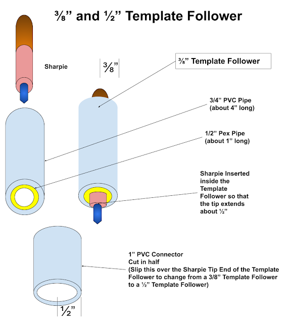
I cam up with the idea of making a Template Follower

The concept is simple. Insert a Sharpie pen inside of a tube, then hold the tube vertically against the template (Foam or cardboard cutout) laying on the material to mark up. Then move the Template Follower around the edge of the template, the tip of the Sharpie marks the material.

The Follower is easily made: Just cut a piece of 1/2" Pex piping about 1" long ( it actually needs to be long enough to allow the Sharpie to be inserted into one end such that the tip of the Sharpie is protruding from the other end of the Pex by at least 1/8" of an inch. Then that piece of Pex is pushed inside of a piece of 1/" PVC Piping about 4" long such that the PEX protrudes about 1/8" from the PVC Piping.

That makes a 3/8" Template Follower. A 1/2" PVC pipe connector will slip (tightly) over the 1/2" piping, so I simply cut a 1/2" PVC Piping Connector in half across it's diameter and with that slipped over the 1/2" PVC piping, it converts to a 1/2" Template Follower.