Thursday, December 21, 2023

Installing Bougerv Fridge Freezer

Installing a 12V Portable Car Fridge Freezer

We're planning on a six week cruise to Georgia ( or at least as close as we can get dependent upon the weather. ) in April 2024 and wanted to increase the amount of cold storage we have aboard.

The Bougerv CRPRO25 26 Quart 12V Portable Car Fridge Freezer looked like it would big enough for holding quite a bit of cold or frozen food/drinks and not too big to exceed the space we have on the boat to keep it secure.

It arrived on time and was easy to setup and test.
We loaded a few bottles of water, plugged it in to a 110v outlet at home, turned it on and let is sit. 

It quickly went down to below freezing and we soon had a few frozen bottles of water.


I was pretty sure it would fit sitting on the seat at the front of our Aft Berth and we set it up using the hold downs and some webbing for our trip up to Lake Boca over the Oktoberfest HISC Cruise.  We set the temperature to 45ºF and left it running for the long weekend. It easily held all of our 'bottles' and 'jars' that would normally go into our regular freezer/fridge aboard. That made a huge difference to our cold storage. My only disappointment was in my choice of the size! I would have gotten a bigger unit as it would fit in the same space. But that's a minor disappointment. I'll not lose any sleep over it.

The only issue with it being mounted on top of that seat is that we lose storage space and access to the small storage locker beneath the seat. So I figured that if there was a shelf mounted higher up, then we could put 'stuff' below it and also have access to that locker.

I came up with this design ( sorry it's not 3D ) 

Shelf Construction


Plan is to make it from Marine Ply, finished with epoxy. 
The shelf will be supported by a brace screwed to the bulkhead another along the seat back and a triangular brace below the aft end of the shelf.

The Fridge Freezer will be strapped down with webbing straps on either end. 

I did notice a voltage drop indicated on the unit's digital display, I'll check the wire gauge of the supply to the 12v outlet. It should be at least 10awg ( I use the BoatHowTo ABYC Wire Size Calculator

Then I had a thought! Would it be worth it to make the shelf removable.
If it were, then either hinge it upwards against the seat back or just lift it out and stow.
The hinge option will not work. The angles are not 90º
To make it removeable, I would hinge the aft edge support brace to the underside of the shelf.
To much complexity for my woodworking skills, so it' going to be fixed.

Ok, plan  done.
Steps:
  1. Make a template as the shelf is anything but rectangular
  2. Cut a piece of ply for the shelf and the three support pieces
  3. Hot glue everything in place to check fit - adjust a needed.
  4. Coat everything with an Epoxy resin.
  5. Install
  6. Make straps to hold down the fridge/freezer.
Made the hot glue gun templates in about 30 minutes today. There are 4 parts:-
  • Outboard Support 
  • Aft Support
  • Forward Support
  • Shelf

I cut the support pieces from a piece of ply I had in the Garage and sanded them down - a quick trip to Lowes Hardware for a piece for the shelf. 4' x 2' x 1/2" ply.

The Outboard support piece is not cut to length, I'll do that after the Forward and Aft support pieces are screwed into position.  Talking of securing the supports, The forward support can be secured using SS screws into the wooden bulkhead between the aft cabin and the galley, but the outboard support is fiberglass, so I'm going to use nut rivets & screws.

Making progress. My templates didn't account for the angles where the pieces meet but I have them all marked out and ready to cut. I could get to this during a short ride from the Marina where Eximius is on land right now but splashes on Tuesday. 

That happened!

We splashed from Playboy Marine at 0800 Tuesday December 19th. We had Patagonia Marine Services paint the bottom and apply a fresh coat of PropSpeed - as always, they did a great job, the Teams down there always do. 

From Playboy marine, we slowly motored up the ICW to Lake Sylvia, I was checking the new Packless Shaft Seal ( PSS ) for leaks. There was a leak - just a drip every minute or so, from the Vent Hose connection. Also the vibration was higher than normal, looks like my alignment was not as good as I thought. 


Anyway, I was able to install the new BougeRV Fridge Freezer Shelf in the Aft Berth. My woodwork would not win any awards but it's very functional. 

The design is longer than needed for the 26Quart unit we have, but I figure, if we ever replace it we'll get a larger one.

The 12v power outlet will come up from the seat locker behind the seat back and the unit will plug in, hopefully no need to drill a hole in the shelf.

The shelf is plain plywood right now, but I'll take it out after the New Year's eve cruise and give it a coat of epoxy with White pigment.


The unit is held down with 1/8" braided line right now, but I'll make some webbing straps with plastic buckles.

As mentioned, there's room below the shelf for a couple of boxes, either provisions or tools, I always need more space for tools!


Another deciding factor for the position of the shelf was where the lid would open. 

There's plenty of room for the lid to open up and swing back against the bulkhead. 

I'm really pleased how this worked out. 

It's convenient being right inside of the door of the Aft Cabin.

It really does not remove any space from a guest that might use the Aft Cabin

It's mounted beneath the LED lamp so it'll be easy to see the contents.

Just what we needed.

I'll get the power setup before our NYE cruise.


See you on the water.

Paul


Friday, December 15, 2023

Replacing the Bilge Pump

Replacing the powered Bilge Pump 

It was working ok but it's 8 years old and due to be replaced.

We have 4 bilge pumps onboard. 2 manual, this one - non-automatic 2000 GPH 12v and our Dry Bilge Pump.

The main one, this one, is 8 years old, and it's just time to replace it.

The hold down clips ( those two red bits on the sides  above the base ) had broken a while ago and I had replaced them with Zip Ties.

When testing the Bilge pump before leaving the dock, I noticed that the 'Manual' operation did not work. Automatic worked fine, so I figured there was a wiring issue somewhere but it could wait till we got to the Haul Out Yard at Playboy Marina.

The replacement was easy:- 
  • Dry the bilge so that no water would get into the screw holes when the base is removed.
  • Cut the wires from the old pump close to the Butt Joints in the wires from the control switch. 
  • Cut the Zip ties to release the pump from the base. 
  • Remove the 4 screws holding the base to the bottom of the bilge.
That's the demolition complete.


This wiring diagram was from the BoatUS.com site but it's basically the same as the one included in the installation sheet that came with the Bilge Pump.

Our wiring is slightly different. The join in the wires from the pump and float switch are actually on a Terminal Block that is behind our electrical panel at the Nav Station. My reason for doing that was to move the join from the bilge area.


With the old pump removed I spent a few minutes cleaning up the bottom of the bilge, it's pretty shallow on Eximius compared to some other boats. It cleaned up pretty good and I was able to remove the old 4200 sealant from the holes and applied some fresh 4200 to seal them.

Screwing the base back onto the bottom of the bilge and seeing the sealant squishing out was reassuring. 

I cut back the old wiring close to the original heat shrink tubing and slid some 1/4" Heat Shrink tubing over the wires. Then I crimped Blue Butt joints onto the supply wires. Next I slide a larger Heat Shrink tube that was long enough to extend pass the ends of the butt joints over the whole assembly. With that done I just needed to crimp the pump side of the butt joints onto the pump wires and use my heat gun to shrink the tubing to completely seal the wiring joint.

I knew that the wiring to the pump was ok as the old pump ran when I operated the float switch, so the issue had to be in the wiring from the electrical panel to the terminal block. I opened the panel and straightaway could see the spade terminal on the Manual side of the switch had pulled off. Pushed it back onto it's terminal and tested the pump on Manual - works. Operated the float switch - works! All done.

The issue with the spade connection on the switch is just another reminder that I really need to work on that electrical panel. One more reminder!  It's on my to-do list and just moved up a notch.

Pump working - next job on the list - Packless Shaft Seal ( PSS )

Getting close to being back in the water.

Paul

Thursday, December 14, 2023

Replacing the Prop Shaft Seal

Replacing the Shaft Seal on our Prop shaft

While searching a the water leak ( turned out it was from the hot water tank ) I noticed that the PSS Shaft Seal was showing it's age. The boat was out of the water, we're delayed from splashing for a few days to the weather so I bit the bullet and ordered a replacement shaft seal.


 This is what the new one looks like ( currently shipping NDA from Defender ) $302 = $352.05 inc. Shipping & Tax.

The currently installed Packless Shaft Seal - PSS does not have the barbed water fitting which ensures that the inside of the fitting is water lubricated.

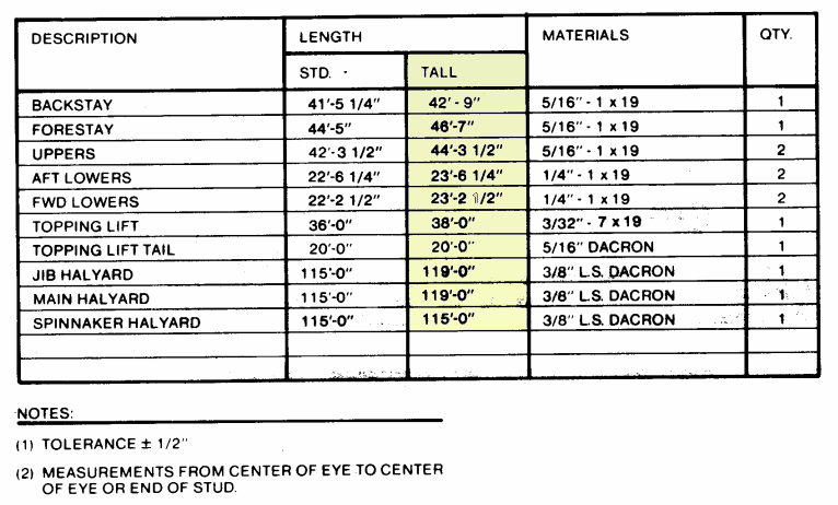
I looked up the size in the Catalina 34 Owners Manual. The shaft is 1" and the shaft log in 1 5/8" OD 

The PSS part number is 02-100-112

The total cost from Defender was about the same as just the pre-tax cost from WM. 


The Old Packless Shaft Seal 

That photo shows the Prop Shaft, the Packless Shaft Seal ( PSS ) and the flange that connects the Prop Shaft to the Gearbox. 
Note the black line on the below the PSS, it extends 360º around the inside of the hull and under the deck of the aft cabin. That's splatter from the old PSS! Basically the PSS is failing ( it's at least 8 years old). The sealing surface between the flat surfaces of the rotating stainless-steel rotor and the stationary carbon flange eventually wear and then the seal fails, it's not a sudden catastrophic failure, it just wears out.  PYI ( Manufacturers of the PSS ) state a 6 year maintenance schedule. Ours is at least 8 years old!

Step 1. Remove the hose clamps.

There are Four clamps, two hold the aft end of the bellows to the shaft log and two hold the bellows to the carbon 'Stator'  

The old clamps were of the perforated type, so they went straight into the garbage.

Next I removed the two set screws from the Shaft coupling, I figured that it would be easier to remove them before separating the flange from the gear box drive flange.  It was, but it was not easy! The set screws had Square ends rather than hexagonals, so the only tool I had that would grab them enough to allow unscrewing them was a 14" Pipe Wrench.  There's not that much room down there and access is for really small people! It took nearly and hour just to remove those two set screws.
Once they were out, the connection to the gear box was easy.

Getting the coupling off of the prop shaft was not pretty! There was not enough room for me to use my three leg puller between the end of the shaft and the gear box, so I had to resort to applying a Sudden High Impact Tool - Hammer! striking the aft end of the coupling. That took another half hour. It finally came off and I was able to remove the shaft Key.

I cut the bellows, removed the 4 set screws from the Stainless Steel Rotor of the PSS and was able to pull the rotor off of the front end of the shaft.

Time for a clean up. Basically I used Soap liquid to wash down the whole area and lots of shop paper towels. 

Preparing the shaft for the new PSS involved sanding it with wet-n-dry paper. I stared with 80 Grit to take off the edges of the key slot and the concave dimples where the two set screws grab the shaft and to ease off the dings caused by my heavy hammering getting the coupling off.  Then it was more sanding using 220, 600, 1500 and finally 2000 grit W&D paper.  

I tested the fit of the SS rotor by using the old one, a light film of dish liquid on the shaft and the O-rings of the old rotor and it slid nice and easy over the shaft, not catching anything.

Next I cleaned the outer surface of the shaft log, just a couple of minutes with 220 grit paper and a washdown with soapy water. 

Now everything was clean and smooth. I scrubbed my hands to ensure I didn't get any contaminates onto the shaft or the new PSS. 

Easing the two aft hose clamps on the new PSS Bellows, I slid the bellows onto the shaft log. PYI advise not to push the bellows to far onto the shaft log however, the build the shaft log does not allow for the bellows to go that far, so no issues there. 

I rotated the PSS bellows so that the hose barb on the forward edge of the bellows pointed upwards. Then I tightened the clamps around the bellows at the shaft log end.

Wiping down the face of the carbon Stator and the Stainless Rotor, and then applied soap liquid to the shaft and the inside of the new Rotor. The new rotor fit nicely over the smooth prop shaft and was slid down to the Stator end of the PSS.

I cleaned up the Shaft to Gearbox coupling and slid that over the end of the Prop shaft ensuring the key was correctly positioned.  

The old bolts from the coupling were showing signs of thread damage, I purchased four new nuts and bolts and spring washers. I used the new bolts to attach the coupling to the gearbox tightening them just enough to make a snug fit, I'll check the alignment when the installation is complete.

With the coupling installed, I gently tapped the end of the prop shaft from the outside to get it fully inserted into the coupling, mindful of the fact that it applies pressure to the gearbox.  With the shaft now correctly positioned, I installed the new set bolts. ( I had also purchased new bolts to replace the square ended screws) to secure the coupling to the shaft.

Now that the shaft was in it's correct position, I moved the Stainless Rotor aft to touch the Carbon Stator and measured from the front edge of the Stainless Rotor to the aft edge of the bellows = 7 1/16".
With the set screws inserted into the Stainless Rotor but not touching the shaft, I compress the bellows by pushing back on the rotor until the distance changed from 7 1/16" to 6 5/16" = a compression of 3/4" as prescribed. 

All done except for the ventilation hose. I stopped by ACE hardware and picked up about 12' of 3/8" ID reinforced hose. I have clamps on the boat. 

Hose installed at the PSS and ran back below the Aft water tank then up to the Stbd side under the combing. No loops in the hose in order to prevent syphon back down the hose.

The hose is zip tied to the existing hoses that run from the aft locker and tank area to the under sink area.  Getting into the aft locker is getting more difficult, I'll have to practice some more boat yoga.

I also checked the Alignment, less than 4 thou" pretty darned good.

The boat is ready to splash on Tuesday 19th of December.  

See you 'on top' of the water.

Paul

Replacing the Depth Transducer Thru Hull

 Replacing the Thru Hull for the Depth Transducer.

In February 2021, I replaced the old Airmar Depth, Speed, Temperature Transducer with the new NEMA 2000 DST 810, however I did not replace the Thru Hull as the boat was in the water.

Each time we return to the dock, I remove the DST 810 and replace it with a dummy plug. That dramatically reduces the amount of growth on the transducer - it actually stopped the 'S' part of the transducer working until I cleaned it off.

The reason for replacing the Thru Hull is simple! Water Water Everywhere and not what you want inside the boat. Pulling the Transducer out of it's Thru Hull would result in a massive ingress of water spewing up into the boat. I'm pretty good at getting the plug in as soon as the Transducer is removed, but it's still about a gallon of water and if I miss the spot, then it's a lot more.  The Thru Hull fitting that came with the new Transducer has a sprung valve inside that significantly diminishes the water ingress.


Step one - get the old Thru Hull out. The boat was on the hard for a bottom job so no water coming in :)

Getting the transducer out was not too difficult, I used my Vibro tool with the cutting attachment to cut into the plastic of the Thru Hull. 

The retaining ring nut didn't want to unscrew, did I see some 5200 in there?

I used a wrench to break off bits of the Thru Hull, had to be careful not to damage that hose, it's a bilge pump hose.


Making progress. I can see daylight.

Probably spent about 10 minutes getting this far.


Finally got it out.

peeled off the old sealant and sanded it down ( after this pic ) then cleaned the inside area.

I sanded the outside too and formed a countersink on the underside of the hole to ensure the new sealant formed a water tight seal.

Peggy was with me, so after cleaning the area with Acetone and applying 4200 to the outer flange of the new Thru Hull and on the area around the Thru Hull on the inside of the hull, Peggy held the fitting up from the outside and I slipped the rubber ring around the threaded portion of the Thru Hull protruding inside the hull. Then on went the retaining ring nut. As planned, 4200 squeezed out of the edges of the ring and, outside, the flange of the Thru Hull. That's not going to leak!

Before tightening it all down, we made sure the Arrow on the outside of the Thru Hull was still pointing forwards - not sure why - but it was perfect. Good Job Peggy.

New Thru Hull installed.
Yes, I know, it's crowded down there. 

The blanking plug can be seen laying on it's side at the bottom of the picture.
It has a yellow O-Ring, so does the Transducer but you cannot see it when installed into the Thru Hull.

The previous Thru Hull required black O-rings, slightly different in size.

Plan is to splash the boat on Tuesday 12/19 - I'll know if it seals correctly then 😉

Of course, I'll inspect it before they remove the Boat Lift Slings.  Check out my post about replacing the Packless Shaft Seal - I'll be checking that too!

See you on the water.


Friday, November 10, 2023

Replacing the Topping Lift

Time to replace the Topping Lift

Actually getting the boat out under sail for the Palm Beach Regatta on May 6th, we found that our Topping Lift was too short! While screwing up the process of Reefing the Mainsail, the bitter end of the line slipped through the line clutch and I had to go up to the mast in order to secure the Boom by securing the line on a spare cleat on the mast ( lot's of sailor terms there  - sorry ) 

The "Topping Lift' is a line that hold up the boom when the sail is not under tension. It's important, without it the Boom can crash down onto the Top of the canvas over the cockpit cabin entrance or down to the deck on either side.

The Reefing process - method of reducing the amount of sail in anticipating heavy winds - is to Stop the Boom falling when the sail is lowered, lower the sail, haul in on the two reefing lines, put the sail back up till it's taut and then ease the Topping lift.

Our problem was the skipper ( me ) forgot and didn't take the weight of the Boom before lowering the sail, so it went 'Boom!' when it crashed down on the port side towards the deck.

Ok, so the correct method for us to Reef is:
  • Take the weight of the Boom using the Topping Lift and and secure it in the Line Clutch
  • Ease the Mainsail till the Reefing points are down at the boom.
  • Tighten the two reefing lines 
  • Haul up the Mainsail to it's new shortened height
  • Ease the Topping Lift line and resecure it in it's Line Clutch.
Now, the Topping Lift line needs to be about 6' longer so that it never slips out of it's line clutch.
Original Topping Lift setup

The topping lift line runs from the cockpit line clutches, forwards to a multi line manager, over to the base of the mast and into a block where it turns up towards boom, then it runs along the outside of the boom to the aft end of the boom to another block then it turns up to a block that is secured to the wire line that goes to the top of the mast. From that block on the lower end of that wire, the topping lift line goes back down and attaches to an attachment on the end of the boom.  To lift the end of the boom we simply pull the end of the topping lift in the cockpit and that lifts the end of the boom, the line is then secured within a line clutch. To ease the boom down, we simply ease the topping lift. Got it? 

To change the line.
  • Tighten up on the Lazy jacks
  • Ease the Mainsheet ( so that's it's not trying to pull the boom down ) and the Vang ( ditto )
  • Remove the old Topping Lift line
  • Feed the new line along the path of the old one
  • Feed the new line through the Line Clutch
It's that easy. I'll time it, should take about 20 mins ( Peggy says that I think everything takes about 20 mins. )

All done. Now the boom could drop all the way down to the deck and there would still be enough line in he cockpit to take control of the boom.  We're ready for the next regatta up to lake worth.

:)

See you on the water.


Sunday, September 17, 2023

Broken boat bits

 Broke but didn't know my boat was in trouble.

We went down to the boat to clean up after a 100mile trip over the labor day weekend. Clean up included picking up the couple of things we left on the boat after the return to the dock on Tuesday, Scrubbing down the deck and resetting the Mainsail cradle cover. 

Resetting the cradle cover simply because the sail had flaked onto just the port side of the boom when we last lowered the sail. In order to sort that out, we had to raise the mainsail, it seemed it required a lot more effort, I thought that was due to the two reefing lines jamming on the boom. 

Nope! That's the first bit to break - the block at the base of the mast had broken! 
This was the new block I installed just a few years ago.

It was being used to turn the Main Halyard and the Main sheet at the base of the mast to the turning blocks on the cabin top and then to the cockpit under the Traveler & dodger.


This is how it looked when I realized the side of the block was broken. The broken piece was sitting on the deck beneath the Dingy.

Now this breakage is not a fault in production or design.

The problem was that when I installed it, I did not review how the lines lay when under full tension! 

With the Main halyard under tension, and the mainsheet tight, the block was turned at an angle that had the Main Halyard rubbing on the cheek of the block, and when at full tension ( Main hauled to the masthead ) the composite side of the block just couldn't take it and the line shredded itself on the broken edge.

Result: Replace the blocks and the  Main Halyard.
I was able to buy new 7/16" New Halyard at Sailorman in Fort Lauderdale and a pair of Seldon blocks from Nance & Underwood in Fort Lauderdale - they were about $55 each.

Back at the boat, I simply sewed the end of the new line to the end of the old main halyard and then pulled the line from out the top of the masthead and thus pulled the new line up inside the mast and back down to the deck. Removed the old line, heat treated the ends of the new line and threaded the new line through the new block, turning block and then through the line clutches on the cabin top under the dodger. It only took about 90 mins - that was because I played around with the direction that the lines went from the turning block to the new blocks so that there was no rubbing on the block sides even when the Halyard was under full tension.
Lastly, I used the excess 7/16" halyard line to replace the worn out Vang line and ran that back to the cockpit too. Now I  should install a new cam cleat under the dodger on the cabin top so that I can remove the cam cleat that is part of the lower vang line block - that way it will be easier to adjust the vang from the cockpit.

Ok, first broken bit fixed.

Next fix was not because something broke - My favorite HISC hat took a swim when we were heading down the ICW last weekend! Normally I would simply have pulled a U-turn and recovered the hat, but it was probably the busiest day of the year on the ICW - Labor Day! and just too much boat traffic to risk that maneuver for a hat - I was due a new one anyway. Luckily, our sailing club had a general meeting this past Thursday and I was able to buy two new hats - you know, one for spare!

The only other thing that needed fixing was getting our Propane tank filled - we'll go to the boat in the morning and pull that out for a refill at the local store.

Our trip up the ICW from Port Everglades to Lake Worth and back was an awesome Labor Day cruise for our sailing club and if the only issue was a broken block then I'll take that.

See you on the water.

Paul


Saturday, July 29, 2023

Soft Start Install on Dometic ECD 10K Air Conditioner

 We added a Soft Start to our Dometic AC System on board our Catalina 34 Sailboat

We have had our Dometic ECD 10K AC unit since 2016 and we would power it at Anchor with our Honda eu2000i Generator, they worked well together.

Then I upgraded the electrical system on our boat to a Victron System which is really clever, even too clever!  When we run the generator and turn on the AC, the Victron would detect that the generator output was insufficient during the AC Startup and it would then start powering the AC from our LiFePo4 Batteries. That's great, until the battery power is too low and then we're without DC power. But we could run the Multiplus in Charge only mode and recharge the batteries, but that process is a pain.

Researching pro electrician 'Google', it seemed that a Soft Start would solve the issue.

I contacted Dometic and they confirmed that a soft start would help but when I contacted a local dealer, I found that the recommended Soft Start device would cost $700 !!!!! Wow!  Searching the web, I found several vendors that sold similar devices at over $300 but then I found SpartanStart for $180, a significant difference from the local dealer $700 for the Dometic device. I called Spartan and they recommended the SpartanStart - Softstart and advised that if I had any issues with the install I could call them and they would walk me through the process.


Installation was easy! The AC unit is beneath our V-Berth, so we removed all of the bedding, mattress and locker covers from the V-Berth

Step 1: Connect Shore Power and turn on the AC - Just to make sure it's working normally.

Step 2: Disconnect Shore power

Step 3:  Remove the Cap on the top of the compressor that covers the electrical wiring that connects the electronics box to the AC unit. There's a single screw that also secures the Ground terminal to the Compressor. 
Underneath that cap are the connectors to the compressor, there's 3. Run, Start and Common. Colors are as shown in the pic below.
Now that I knew which color was what, I replaced the cap.


Step 4: The individual wires are inside a plastic, split, conduit. I separated the conduit about midway from the top of the Compressor and the Electronics unit, and pulled the three wires needed out of the conduit.

Step 5: I cut the wires one at a time and crimped them to the correct wire as shown in the diagram above.  That's 6 crimps. 

Step 6: Time to test;
First I reconnected shore power and turned on the AC unit, after it's typical delay it turned on and started to pump out cold air.  Looking good so far.

Next I disconnected shore power and connected it to our Honda eu2000i generator and switched it to, what I call is 'Turtle' mode - it's a power saving option. The generator runs at minimum power and adjusts the power on demand.  Time to test the AC on the Generator. 

Turning on the AC system, it had it's usual delay, not noticeably different from when the AC starts up on Shore power.  The AC ran and the generator barely changed it's output.

The AC unit pulls about 900Watts when running.

At this point, the AC was running and the Victron system was showing that all power was coming from the Generator ( shore power ) and that no power was coming from the Battery.

We left the AC running and tested it running on the inverter powered by the batteries. I simply switched off the master shore power switch. The AC didn't even blink, it continued running but now pulling the 900Watts from the Battery ( 12.8v x 100a *3 = 3840 Watts ) 
With the AC running off the batteries, I turned the master shore power switch back on and after the normal delay the Victron Multiplus turned on and started powering the AC system, there was plenty of  power available from the generator, so the Victron Multiplus started to recharge the batteries.

With everything working correctly, time for a bit of wire management, and a few zip ties pulled it all together.

This was a major step towards our cruising plans. With the current heatwave that is being experienced all over the East coast of the USA, we believe we'll need the ability to run the AC from the Honda Generator.

See  you on the water and if we're running our generator at Anchor, then it'll probably be for the AC unit and it will probably be running in turtle mode.


Sunday, July 16, 2023

Sailboat Sunshade

 Making a Sailboat Sunshade for our Catalina 34 Sailboat

We have a 10K AC unit on board and a Honda eu2000i generator to keep us cool in the boat, but the heat transfer through the deck into the Main Cabin and the V-Berth is incredible and really puts a strain on the AC unit. Solution: Make a Sunshade to cover the Deck from the Bow to the Cockpit ( The Cockpit has a Dodger and Bimini so that is typically well shaded.


The fabric that I have chosen is from Sailrite, $11 per yard, 150" wide - that's 12'6" or if cut in two, it's 6'3" or 5'7" when double hemmed.

It's not a solid fabric, so rain should pretty well pass through it and it will also not act too much like a sail.

The material is easily sewn and I plan to add grommets along the edges and use bungees or ties to secure the panels to the boat.


I plan on making 3 panels.

The Purple panel will cover most of the foredeck, I hope it will extend slopping down towards the bow so that the rain tends to run away from the mast. The Red, Port and Green Stbd panels will cover each side and extend from the mast, aft to the Dodger, the sail cover will slope down towards the lifelines.

By making it three panels, each panel will be more manageable, I'll make a sack for each of them.

The aft end of the port and stbd panels will connect to the front of the dodger at the grab rails. 

My purchase was 10 yards of the material, that should be plenty. I have purchased shade material from sailrite before but it was a lot less expensive, this is a very nice material. On the sailrite site, it is "Shade/Privacy Fence Fabric Blue 150"


From a scale drawing, I figure the sizes to be ( allowing for seams ):-
  1. Purple: 
    1. 11' wide aft edge -> Make that max width of the fabric to allow for slope and 3" hem each side for the grommets or 12'
    2. 3'6" wide on forward edge -> make that 4'6" to allow for slope and hems
    3. 10' 6" fore-n-aft - plus 6" for the hems or 11'
  2. Red & Green
    1. 5'4" wide  -> Make that 1/2 of the max fabric width or 6'6"
    2. 8'9" fore-n-aft -> 9'3" with hems
That's one piece 12' x 4'6" x 11' Trapezoid
Two pieces  6'6" x 9'3"

The extra widths will allow the fabric to slope down towards the sides of the deck.

I'll add a second layer to reinforce the areas where the grommets will be installed. I'll use Brass or Stainless Steel Grommets

They will need slots for the shrouds, no need for zippers to close them I'll just put loops and toggles to close the slots. Again, reinforce the edges of the grommets.

Also, they will need cords to attach them to the mast and the lifelines, however, I might run a line horizontally from the shouds back to the dodger grab rails, that would possibly improve the deck access forwards, else it will either mean crawling to go forward or unhitching the shade panels on the side in order to walk along the deck.

I'll double check the measurements next time at the boat and establish the distance from the mast to the shrouds so that I know where the slots start, will also have to measure the distance from the front and back edges of the mast to each shroud.

Ok, the plan is made. Get the numbers and start to make them.

Foredeck cover - ready to fit.

The first piece is cut and sewn, only took a couple of hours. It has a 1.5" double hem all the way around. That's wide enough to install gromets in the long sides and the corners. We'll go down to the boat tomorrow to do a test fit. Install the gromets and it should be ready to go.


Oh! good news too. The Foredeck cover folds up to about 18" by 12" by 6" and that is the largest piece. 
I'll make stowage bags for each of the three pieces 


Port & Stbd Covers complete.
That's the last two pieces done. Bags and all. Fit great. I might put another grommet in the outboard edges but will wait till we have tried them out this weekend.

Where to store them when not in use?

I'm guessing that the fabric will not last long if left in the South Florida Sunshine 24/7, so the plan is to stow them below but where?

No room in the anchor locker. I don't want them ( the 3 cover bags ) loafing around in either the main cabin or the aft cabin and the V-berth is pretty well reserved for our belongings.

That leaves either the Port Cockpit locker or the stern lazarette. There's room in both but the least used is the lazarette. I'll put some hooks on the port side in there and hang the bags.  I'll also put colored tags on the bags to match the covers - Red for port side, Green for stbd and Red & Green for the bow cover.   

Ok, we're into prep of the boat for this weekends trip up to Lake Boca. As always, I have a long list of things that I need  get done.


We used them in earnest for the first time over the Oktoberfest weekend. What a difference! Ok, so the weather was perfect and had dropped a few degrees, still in the high 80's low 90's, Fahrenheit but the cabin stayed so much cooler that we didn't even need to run the Generator while at anchor on Lake Boca.

I'll add a few extra pics when I get the chance ( ie, when I'm on someone else's boat and can see them from a distance.


See you on the water - if we're at anchor then we'll probably have our 'tarps' on. ( they are not tarps, but the material is a similar color to blue tarps 😂


Friday, July 14, 2023

Fuel Gauge Failure

 Our Fuel Gauge Failed 

On the last couple of trips, our Fuel Gauge became erratic. I would drop from showing 3/4 full to Empty or some other significant change in reading. I would normally put that down to a bad wiring connection however, I rebuilt the entire engine control panel in 2016 and I know I did a really good job ensuring all of the connections were solid. ( Crimped ! ) But still worth checking out the wiring.

The engine instruments are all on a common power supply and a common earth and the wires are connected to the instruments via ring terminals and nut and bolt attachments. All were secure. The other earth on the fuel gauge system is at the fuel tank itself, but that was solid too and using a Multimeter the resistance was less than 1Ω.


Next suspect was the Sender.

It's a pretty simple unit. The float opens/closes a series of reed switches as it moves up or down the shaft of the sender.

That changes the resistance of the sender and the gauge displays the fuel level dependent upon the resistance.

The tank is located on the Port side aft, Access is by removing the plywood bulkhead on the port side of the Aft Berth. 
I removed the sender from the tank and we tested it by moving the float up and down, ah ha! it would intermittently operate correctly, so I have to consider that one or more of the read switches is faulty.

Disconnecting the sender from the system and testing with a multimeter confirmed it was the sender.

I had ordered a replacement Sender and Gauge so that I was prepared if it turned out to be either of them.


The new sender did not work with the old gauge but the new gauge was the same size so it was a reasonably easy swap out.

The Gauge is not just a simple voltage meter!
When the power is applied, the gauge lights up to the selected background color choice then the needle moves from E to F, back to E and then it moves to indicate the current fuel level. It does this very smoothly. I found this a really nice feature, the needle moving in that way indicates that the system is working.


Once the system was wired in, all that remained was to replace the engine control panel, sealing the edges with Butyl tape - that makes it easy to remove if needed. Then secure the wiring at the tank end and replace the wooden bulkhead.

Most of the time taken was in testing the various components and wiring.

Kit details: 100TECH Boat Fuel Sending Unit with Gauge 11"(280mm) 
SUS316 Stainless Steel Marine Fuel Level Sender Sensor 240-33ohm

I opted for the 11" sender rather than the 12" that would still fit, if the gauge reads empty, then we have at least 1.5" of fuel in the tank. Consider it a reserve.

I purchased the kit from Amazon $69.

The only near hiccup was that the float on the new sender is slightly wider ( Dia. ) than the old unit but it fit snuggly. The kit included a new gasket, screws and butt connectors.

Just an FYI, we never fill the tank to Full - I really do not want to risk fuel overflow so when the gauge reads over 3/4 full we stop filling! We always carry at least 2 x 6 gallon fuel cans. So our normal capacity is 23 gallons in the tank plus up to 24 gallons in cans on deck. That gives us about 45 gallons and at 1 gallon per hour, we're good for 45 hours of motoring. 

One last thing: When we are motoring, we have a routine of 'checking the heartbeat'. About every 15 minutes, we'll check the engine status:- Look over the stern to ensure water is pumping out the exhaust, Check the engine Temperature and Fuel level.  If I'm in the cabin and Peggy at the helm, all I need do is tap my wrist with two fingers and Pegs gets the message then checks the Heartbeat.  

See you on the water.

Monday, July 10, 2023

Solar Panel Wiring & Mounts

Managing the Solar Panel Wiring

Currently, the Solar Panels on Eximius have their power wires secured with zip ties down the Bimini Support Stainless Steel tubing. The same type of zip ties are used to secure the wires that run up the Pedestal Support tubes to the electronics at the helm: Chartplotter, Depth Display unit, Auto Pilot control and display as well as the general data display and finally the VHF Remote Microphone.

Those Zip Ties have to be replaced at least once a year due to them breaking down as a result of UV damage.  


While aboard a friends boat this past weekend, I noticed that his wiring is secured using much larger zip ties. The Brand is TR Ultra Heavy Duty Multi-purpose cable ties -- UV resistant,  Black

They are 11.8" long and .49" wide, 0.067in thick.

The pic shows the typical thin zip tie that I get from Harbor Freight and the TR Zip tie. Literally a Huge difference.

The Pack of 50 is sold on Amazon $20, here's the link there are other sizes ( various lengths. ) 

When I install the new solar panels in the next week or two ( awaiting delivery ) I plan on running the wires down the Radar Support Post instead of the Bimini frame.

I see several benefits to using these larger width zip ties.
      1. UV Resistant - We live in South Florida - Enough said
      2. Larger Width - The extra width expands the area of wire reducing point loading.
      3. Appearance - they look so much better than their thin counterparts.

Moving nearer to installing the new Solar Panels !!

I have decided on the rail mounts. Recently, I assisted in the install of 1200 Watts of solar panels on a Trawler, we used Aluminium Rails and mounts to secure the Panels to the roof of the boat. That worked out really well so I'm going to use the same products.


Ok, onto the Solar Panel Mounts.

The existing panels are mounted on top of the Bimini supported by a hodge podge of rails made of Wood or Aluminum square tube or Aluminum U channel. It does not look neat and tidy and the wooden rail is suffering, I'm removing all 3 rails and replacing them with Aluminum Rails


The pieces of rail are only 30" long but can be connected together easily with a solid bar that fits in the square slot.

I have a total of 10 pieces plus 2 half lengths left over from my buddies Solar Project.

So there is 300 inches of rail and the rails are about 60" long or between 2 pieces and 2 + 1/2 piece, so I have plenty of rails and also plenty of the various fittings to attach the rails to the Bimini and the solar panels to the rails.


I purchased additional connector pieces as the kit only had 2 of them, the additional ones are solid but have the same function.


Ideally, the panels would all touch the adjacent panel, but the Back Stay cables prevent the two aft panels doing that, however, I hope that the forward edge of the two aft panels will be able to touch and connect to the front most panel.

Starting this week ( July 11th 2023 )

See you on the water.


Update to include links to the Solar Panel Rail Kits that I used.
The rails are 30" long and can be joined. The aft rail is about 68" long so that is made from two full length pieces and a short one in the center. The other two rails are 60" so just two pieces joined together.

I put rubber plugs ( Black Sink Stoppers from ACE Hardware ) between the rails and the Bimini Tubing to support the rails ( they also act as a water barrier over the holes drilled through the Bimini canvas and the tubing.)

Here's the link to the rail Kits  I had needed two kits for my install.


Wednesday, July 5, 2023

July 4th Cruise 2023

No Wind = more of an RV event than an SV event for Eximius

High tide dictated that we would have to leave the dock on Thursday evening so we loaded the boat Thursday afternoon, it was Hot! so we plugged in shore power in order to run the Air Conditioning. We left the dock about 18:45, it was looking like we would have good weather but no wind, so our plan was to anchor overnight at Sunrise Bay. We dropped anchor before the Sun went down and made a dinner ( see that disaster here

Oh! we tried out our new Anchor Ball in Sunrise Bay and it gets my ***** votes right now. I have it setup for a 12' 1/8" white line from the ring on the ball to a spring hook to attach to the Anchor chain close to the Anchor shaft. That way, the ball will float without trying to pull up on the anchor in waters up to 12' deep. 

It was nice being able to see where the anchor was relative to the boat, it also indicates where it is compared to other boats especially when they are dropping their anchor. The Bay was almost empty, plenty of room to anchor and our nearest neighbor was about 80' away ( we have a digital laser range finder ) and was the type of boat that would not stay overnight - no cabin.

Ouc  cabin was reasonably cool overnight so we slept well although I did get up at 2am to turn off the dry bilge system, it's not that it's loud, but just annoyingly loud enough to cause me to wake from a not very deep sleep. Once the dry bilge system was turned off, I was able to go back to sleep.

We woke up around 7am and had a cereal breakfast with skillet toast and that so important Coffee! The morning was off to a good start.  After breakfast, Peggy took the helm while I hauled in the Anchor Snubber and then we worked together as I pulled the anchor and Pegs kept the boat so that the anchor chain was mostly straight up and down. We wore our headsets and that always makes it easy to communicate. Once the anchor was up, the anchor ball removed and everything stowed, Peggy turned us to the East side of the Bay so that we could turn North on the ICW.

There was no wind, as expected, so we motored up the ICW and easily made all of the bridges. We have a Cheat Sheet with all the ICW bridges listed and the distance and time to the next bridge if we were traveling at 5 knots.  We had the ICW on the nose all the way up to Lake Boca. Not many boats on the center of the Lake, however, we were able to anchor about the center of the North side of the lake. We used the anchor ball again and this time it was really useful.  Most of the boats along that North side of the lake are in various states of abandonment and they are permanently anchored and not necessarily on reliable anchor rodes.  But we anchored safely and the anchor ball helped us know where we were relative to the anchor. Most of the night, the anchor ball was touching our hull, so we were over the top of the anchor.

We had a cooked breakfast of eggs, sausage, tomatoes and skillet toast plus the coffee. Then it was time to cleanup the deck. We get a lot of tree droppings landing on the boat at the dock. While I was sorting out the deck, a guy came along on his JetSki and asked if I knew who had set the mooring ball off of our Bow. I explained that it was our anchor marker ball. He then proceeded to tell me how a boat had broken free of it's anchor and had collided with his dock  - mind you! His dock is on the frontage of his huge home that overlooks the lake. He told me that he pays $250,000 taxes a year for the property and that he had 'poop' in the water by his dock. Then he went on to complain about the boats in the lake emptying their poop buckets in the lake and rinsing them out.

Ok, let's keep this straight. I don't care how much you pay in taxes or even if you don't pay any taxes. In my mind, it doesn't matter - we all deserve clean water and none of us want to swim in a Bay that is polluted by human waste. 

Personally, we take pride in running a clean boat. We just spent $$$$ on replacing the toilet hoses and pumping out the holding tank as well as replacing the Macerator pump on our waste system. I'm happy to report that our system is smell free. Also, the Thruhull for the waste system is locked off and cannot be accidently opened. That's the Law! To my knowledge, all of the members of our sailing club that own boats follow that same law. 

However! When we see boats anchored for months, if not years, in the Lake and never moving, plus there is no mobile pumpout facility close to the lake, then those boats do not 'pumpout' and if there are people living on the boats, they must produce some waste and they need to dispose of that in a healthy manner. By the way! Wrapping it up in garbage bags and dumping it ashore in a trash can is not a healthy manner!

So, I understand the complaint of the home owner about finding poop along his dock - I must admit I have my doubts about that - poop disintegrates in water pretty quickly especially when there are plenty of power boats navigating around the sides of the lake away from the anchored boats. Those power boats are like floating macerators!

Anchoring restrictions are an issue in South Florida, primarily due to boats being used as a really low cost housing option.  But I see no reason why those boats cannot be maintained in a healthy manner and I support local legislation that would enforce that.  

Florida has a program that encourages mobile and static pump facility services. It's probably abused by big corporations taking some of the grant money and then closing the facility ( Los Olas Blvd Marina might be an example of that )  We really do need pumpout facilities within reach of all anchorages. It should be easy to request a pumpout that would arrive within a few days, and local law enforcement could easily monitor that the pumpouts are being used without even visiting the boats.

Ok, end of Rant!

I'll close this post and start a part II covering the great weekend on the water and the parties with the HISC members on their boats.

See you on the water.


Tuesday, July 4, 2023

Replacing the Masthead Sheaves

Replacing the Masthead Sheaves on our Catalina 34 - In the water!


I plan to replace the Standing Rigging on our 1987 Catalina 34 Tall Rig Fin Keel later this year.

My plan  is to replace the rigging while the boat is in the water and not to pull the Keel Stepped Mast.

Pulling the mast would make it a lot easier, but it's crazy expensive here in South Florida. just to have the mast pulled. Just removing the mast and replacing it will cost about $3,000 !!!!! 

So, how to complete the task with the boat in the water?

The Rigging consists of 
  1. Forestay ( $600 )
  2. Backstay ( $1000 )
  3. Port & Stbd Upper Shrouds ( two ) ( $1900 )
  4. Port & Stbd - Fore & Aft Lower Shrouds ( two pair ) ( $1250) 
Rigging materials = $4750 + Taxes and Shipping -- Guesstimate $6000 ( as sold by CatalinaDirect )

The sheaves at the top of the mast are part of the Mast head and there lies the problem. I have gone up the mast several times ( 5 times in one month when our Wireless Wind Transducer Failed ) so I'm very comfortable about going up the mast and do not see any problems working to replace the standing rigging, but the sheaves are another problem because when I go up the mast, I am supported on the halyards that run on those sheaves that I want to replace!!!!

My solution is to install Mast Steps from about 6 feet from the top of the mast, the highest being enough to support me on both sides of the mast while removing the Masthead.

So, the plan would be to measure all of the rigging, purchase the correct size cable and new turnbuckles and any beckets that need to be replaced ( most of them ) and of course, purchase the mast steps.

Then going up the mast and install the mast steps. With the steps in place, I would replace the standing rigging one cable at a time. First I would backup the cable with a halyard or dyneema cable taking the strain off of the piece of standing rigging. Remove the piece of rigging and make up the replacement using Mechanical Fittings.

Next, onto the Mast Head.

There is a halyard that does not attach to the Masthead ( Spinnaker halyard ) I would use this to climb the mast using the other halyards to climb up the mast to reach the newly installed Maststeps.

At the top, I would unbolt the masthead and remove the sheaves, replace them with new sheaves and pins then replace the mast head.

Sounds pretty straight forward, but it is a boat!!!!

Posting this hoping to get some feedback on the project.

Rigging Dimensions


Friday, June 30, 2023

Instant Pot on our boat success and failure

Having had our Instant Pot 6qt at home for a couple of months and I love it. Using it every few days to cook dinners, cakes even cheesecake. So much so that I bought a 3qt Instant Pot for on the boat, although with a little concern about power consumption. We have a total of 3×100AH batteries,  that's over 3kwh if we run them to zero.

Last night I tried the Instant Pot on the boat for the first time and it was both a huge success as well as a dismal failure. 

1st, the Sucess
So the power consumption is 1000 W for the 6 qt model. I think that's right. It's only 700 W  for the 3qt model, and that was not too certain. Different people report different wattages so I didn't know for certain. Because I have ta complete Victron system on Eximius, when I plug something in, it shows me how much power is being used. 

When I plugged in the 3 qt instant pot and set it for high pressure cooking, the system showed the power consumption was 700watts.Thats a good start, but it gets better!

The Instant Pot takes a few minutes to get up to pressure,  it's basically boiling the water inside the Pot. Once it's approaching the pressure level, the pressure lock valve will pop up and the display will soon show the countdown of the number of minutes that were set.

This is where the Instant Pot shines! Once the Instant Pot reaches pressure,  the power consumption dropped to 1 watt! Yes, 1 watt!!!

I was cooking baked potatoes,  OK, they are steamed rather than baked, but I probably cook potatoes every week at home, they are a quick and easy dinner. I make a thick cheese sauce with butter, Ricotta and grated cheese blend adding pepper and salt to taste then topping them with more grated cheese. Delicious! 

On the boat I saw the power consumption pop back up to 700 watts foe about a minute twice during the cooking of the potatoes. 

I didn't time it, but I believe that the cooker only consumed 700watts for about 8 minutes of the 17minute cook time.
Roughly that's 700×8 ÷ 60 = about 90 watthours. And that is about 2% of the available power.

OK, time to fessup on the failure. 
The potatoes cooked perfectly, 17 minutes with a quick release (in the cockpit to avoid the heat steaming the cabin) I then removed the potatoes, added 1/2 cup of milk to reminaning water and a packet of cheesey pasta shells and a couple of cups of frozen broccoli then set the Instant Pot to pressure cook high for 3 minutes. 

Don't try that!!,

After the 3mins of cook time, I unplugged the Instant Pot again and took it out to the cockpit for the quick pressure release. 

Don't do that!!!

Cheesey sauce blew out of the pressure vent!! And things didn't get any better.  I scooped the pasta out of the pot and topped each of the potatoes with cheesey broccoli pasta and sauce.

Definitely not a success! Peggy did a stellar job of maybe eating half, but did not enjoy the meal. I should not really call it a meal, more like a mess.

The good news is that the Instant Pot worked great and consumed very little power but the chef needs to practice..... a lot 

Friday, June 23, 2023

Solar Panel Update - problem with shipping

Solar Panels Damaged during shipping - it's a problem

We ordered 3 x 220 Watt Solar Panels from a company via Amazon. All three were damaged upon arrival. They probably worked, but the damage to the frames was something that I could not hide if they were mounted atop our Bimini on Eximius. Everytime I board the boat, I would see those damaged panels and you know how those scratches itch! So I returned them. I took a couple of weeks to get the money back into my amazon account. 

I have searched online many sites trying to find a local company where I could pickup the panels and inspect them before taking delivery of them. None! There was one local company that had panels almost the size I needed but they were literally 2 times the price! So 3 panels would go from $700 up to $1400!

I have previously purchased BougeRV panels, worked great both on the boat and at home ( Solar Hot Water Pump system ) so I ordered three 200Watt panels from them. Their reviews on Amazon were really good and they included details of their packing in their Ad. 


Yesterday, the 3 panels arrived. Two were perfect but the 3rd was destroyed, it had obviously been damaged in transit, the frame on one side was actually bent, the box was concaved on one side. The glass on top of the panel was shattered into several thousand pieces, totally ruined.

Of course I contacted the seller and am expecting a response within 24 hours, of course, it's Friday, so I don't expect a reply till Monday.  I was able to talk to customer service, they were on the ball and didn't hesitate to escalate it up to the Returns dept. That's a good sign!

The good news is that I can go ahead with the install, I'll use one of the panels as a template for the 3rd panel and mount the two good panels, new wiring and the new MPPT controller ( see my other post on the entire process of planning and installation.)

Meanwhile, I won't hold my breath until Monday ;)

Paul

Update - Sunday June 25th
BougeRV have been responding and their latest email indicates they are going to replace the panel directly ( not via Amazon ). Their Customer service is staying on top of this issue. They are getting ***** right now. 

Update - Monday June 26th
So far I'm impressed by the customer service at BougeRV, there was an email waiting for me this morning which indicated they are shipping the new panel and that I can toss out the broken one. Understandably, the busted panel is not worth the shipping.