Thursday, March 30, 2023

Installing Balmar Serpentine Belt Kit

Replacing the drive belt on our Universal M25-XP

Our Universal M25-XP Diesel Engine on Eximius our 1987 Catalina 34 is probably 35 years old, it may have been built a couple of years before that. In the 8 years that we have owned Eximius, we have gone through just a few drive belts, but we have had to put up with the Squealing of the belt when the electrical system requested a lot of power from the Alternator and the 'Belt Dust' that is shed over the engine despite the frequent checking of the alignment of the pulleys that are driven courtesy of the Drive -V- Belt.

Over the past year, we have made substantial upgrades to our electrical system, including the engine alternator mounting bracket and the installation of a Balmar MC-618 External Regulator with the intent of installing LiFePo4 Lithium Batteries in place of the current Lead Acid House Batteries. The LiFePo4 batteries can pull a substantially higher charging current than the LA batteries. So having a drive belt system that can drive the engine Alternator is important.

Several of my buddy sailors have upgraded their engines (not necessarily the same engine we have,) with a serpentine belt system. They have been very impressed with the results.

Looking up the details of the Serpentine kits online, I found that one important issue was that the replacement engine pulleys are wider than the existing pulleys by about 1/2".  I checked our engine and confirmed there was at least 3/4" space between the front face of the existing pulleys and the engine sound insulation that is on the back of the cabin steps that form the front cover of the engine space.

I ordered the Balmar 48-USP-M25 Serpentine belt kit from PKYS.com - it has come down in price over the past few months and only cost $472.94 total including tax.

In the online order, I asked if they would confirm that it was the correct version for the Universal M25-XP, their response was that I should confirm the version myself.

A member of the C34 Association suggested that I contact Balmar directly. I did and Mike from Balmar confirmed that I had the correct kit version for our engine. I then contacted PKYS.com and confirmed the order. 

Rod Collins from marinehowto.com advised that I should ensure that the crank pulley on the engine is a 3 hole fitting to match the kit. It does ( but I had to go check )

Here's the kit:
I expect to have to remove the Alternator in order to replace the pulley, there's a local shop that can do that.

I confirmed that the Coolant Pump Pulley is replaced by the new one ( the pulley on the left of the picture.

The Crankshaft pulley fits over the existing crankshaft pulley.

Note there are two of the serpentine belts, one is a spare.
Of course, some of the kit components are out of stock. 


Here's the plan.

Remove the engine cover ( cabin steps ) and remove the existing V-Belt.
Try to remove the Alternator Pulley - If I cannot get it off then remove the Alternator and take it to a local shop and have them replace the pulley.

The new Crankshaft pulley fits over the existing pulley, I have already confirmed that the bolts are not seized, so install that pulley.

The same goes for the Coolant pump Pulley.

Install the new Serpentine belt and adjust the belt tension by adjusting the Alternator support arm ( note that I'm using a modified support arm that I had made locally )

Test it, run the engine over the full RPM range, Check for belt slippage ( squeal ) 
Recheck Belt tension.

All done.

RIGHT! Boat projects never go that easy!

Ok, everything is ordered, should arrive by February 25th(ish - USPS)

Our plan ( Peggy will be helping offering moral support ) is to go down to the boat when the kit arrives and get down to it. We're taking the boat out for our sailing club's annual Circle Raft up on March 3rd.  -- No pressure --

2023.02.24 09:00 - Just received notice from PKYS tracking that the package should arrive today before 9pm although it's 'out for delivery' right now.
Our schedule is Busy Saturday, We don't go to the boat at the dock on Sundays, but I should be able to start the install on Monday Feb 27th. It's going to be tough but I was planning an article for the Catalina Mainsheet magazine about the install, that would be due delivery by March 1st. - NO PRESSURE -

1st attempt to install the new pulleys.

Well that hit a wall as expected! I was able to remove the Coolant Pump Pulley and the new pulley fits the drive flange where the old pulley was installed.- that's on the Up side.

I was able to remove the outer pulley on the Crank Shaft ( the existing pulleys are all twin belt pulleys ). Basically I removed the three bolts that secure the pulleys to the crank shaft and remove the keyway hex bolt then use a 3 Jaw puller to remove the outer pulley and expose the original inner pulley.

The new Balmar Crank Shaft pulley is mounted over the existing inner pulley, but it does not fit.
The Original Inner Pulley is 130mm diameter
The new pulley's internal diameter is 127mm
( That's measured with my plastic Dial Caliper, so not likely to be that accurate)

And I confirmed that I cannot remove the pulley from the alternator, so I will have to remove the alternator and take it to the local shop and have them remove the old and install the new. But first I'll have to figure out the issue with the Crankshaft pulley. There's a local Kabota dealer just 10mins from my house and they are always helpful, but I'll also contact Balmar to see if they have a pulley that will fit over our crankshaft pulley.

I put everything back together and ran the engine for 10 mins to make sure all was well. We're taking the boat for a weekend trip starting Thursday (tomorrow) evening. We're good to go.


The task continues.

I finished work early the other day ( Thursday) and went to the boat to see if I could pull the Engine Crankshaft Pulley using the same puller as in the pic above.  There's a heavy duty tab washer keeping the Nut on the shaft, I was able to bend that back out of the way and then used a Socket and wrench to remove the nut. It took a few whacks of a hammer to loosen the nut but it came off after a few minutes of effort, then the puller easily removed the pulley and the 'key' fell out as I removed the pulley from the shaft. I was pleasantly surprised how easy it was to get that off.

Next item to tackle was the Alternator pulley. I didn't think I would have any chance to remove it although I did have a suitable socket. The alternator spins so easily I didn't think it was worth trying. So I disconnected the main battery +ve at  the battery and then  I removed the Alternator putting a piece of Heat Shrink tubing over the bare end of the big +ve wire  so that I could reconnect the battery in order to keep power available to the Bilge Pump.

With the Crankshaft pulley and the Alternator in hand, I headed to Fort Lauderdale to visit the machine shop and battery / alternator shop. 1st stop was Fort Lauderdale Battery & Electric. They have been really helpful in the past and I think that the majority of patrons go there with a 'problem' whereas I've been fortunate enough to know what was needed and they always come through. I showed them the Alternator and the new pulley. Two minutes later it was all done. Barely had time to warm the seat at the counter.  ( Here's a link to the last time I visited them )  Within 10 minutes of arriving I was leaving the shop with the alternator wearing it's shiney new Balmar Pulley.

Next stop was Tropical Marine just down the road from the Lauderdale Battery & Electric shop. They had made the modified Alternator Support Arm ( here's a link to that article ). They are going to turn the Engine Crankshaft Pulley down so that the new Balmar Pulley will fit over itl, an easy fit. Should be ready this week.

So! Making progress.
Important note. A boating buddy also installed the Balmar Serpentine belt kit on his Boat's Generator. Within just a few hours, the belt was damaged due to misalignment, so I'll be careful to measure the alignment when I put this back together. Probably make a separate post about that, but I think that I should be able to shim any of the pulleys outwards in order to ensure alignment.

Waiting on the phone call from Tropical Marine.

Tuesday, March 16th. Got the call from Tropical Marine, it's ready for pickup.

Wednesday: I drove down to Tropical marine before heading into work today, the new Pulley now fits around the Crankshaft Pulley, it's ready to go. Oh, and all of the holes line up.

I'll work on Monday and Tuesday and take off Wednesday to complete the Serpentine Belt upgrade for the engine. We must  not run the engine yet as our Prop shaft has a problem that the divers should fix in the next few days. 

Wednesday March 22nd.
Well, that was not a real surprise! The belt is too long! 
Down at the boat this morning, I cleaned up the front of the engine with some Spray 9 and a bunch of rags, it looks Spiffy.
Next I installed the Crankshaft Pulley, remembering to apply the TefGel onto the face of the new pulley that touches the old Crankshaft pulley. I did not apply the Loctite to the pulley bolts as I wanted to check the alignment first.
Next was the install of the Coolant pump pulley, that went without a hitch.
Finally install the Alternator that now wears a nice blue Balmar Pulley on the front spindle.

Next was to install the new Serpentine Belt over the three pulleys, and there's the problem. The new belt is at least 1cm too long. The alternator would be sticking out of the access door in the bathroom. 

Grrrr. But what the heck, it's a Boat! 

I called Balmar and the belt is 42" long and they have a 41" belt. They cost $74 each plus shipping.

After picking my jaw up from the floor, it was explained how they would exchange the 42" belts for the 41" belts if I mailed them to their facility in Alabama.

So that's the plan.

Oh, there's another issue. The belt tensioner that I made to use on the V-grooved Pulleys that I have now removed, does not play nicely with the new Aluminum Pulleys. I'll have to polish out the scratches on the surface of both the Crankshaft Pulley and the Alternator Pulley.  At least that's easy as they are Aluminum. 

Ok, held up for a few days. I'll mail the belts tomorrow.

Stay tuned.

Change of plans!

My buddy has replaced the V-Belt on his boat's Generator and had the same issue, belts too long. He suggested I contact VBeltGuys.com. I did, Two new 41" belts arrived 3 days later and cost less than the shipping both ways to balmar. So I'm not sending the balmar belts back - if you know anyone that wants a pair of 42" 10 ridge Serpentine belts free for pickup or shipping --- let me know.

Thursday March 30th.

Went down the to boat, completed the install of the belt and checked the alignment, looks as close to perfect as I think I can get it. Ran the engine, all worked pefectly, the belt did seem to stretch/loosen a little, but I retensioned it in about 5 mins.

Oh! Forgot to mention: When I used my home made belt tensioner to try and tighten the 42" belts ( unsuccessfully ) the tensioner damaged the alternator pulley surface. Today I took a set of fine files and removed any burrs off of the alternator pulley. Note: Do not use a tensioner that might damage the pulleys!

Once the tension was correct and aligned, I removed the bolts for the Crankshaft pulley, one at a time and applied the Locktite supplied with Balmar Serpentine belt kit. Then did the same for the coolant pump pulley bolts. The final thing to do was bend the tabs of all of the locking washers on the alternator support arms and re-run the engine to confirm all was good - it was. 

Phew, so glad to complete this project. Of course, the engine sounds a whole lot better or is that just that my ears are satisfied with completing the project.


Here's all of the info about the kit, PKYS and Balmar, Lauderdale Battery & Electric and Tropic Marine products.

Kit: 
Balmar 48-USP-M25

Cost:
Subtotal: $442.00
Discount: $0.00
Shipping: $0.00
Sales Tax: $30.94
Total: $472.94

Purchased from PKYS Inc.

 https://www.pkys.com

7416 EDGEWOOD RD STE 3
ANNAPOLIS MD 21403
410 280-2267


Balmar: 

https://www.balmar.net

15201 39th Ave NE
Marysville, WA 98271
Customer Service: 1.360.435.6100 x1
Technical Service: 1.360.435.6100 x3


Fort Lauderdale Battery & Electric

2415 SW 3rd Ave, Fort Lauderdale, FL 33315


Tropical Marine  

Tropic Marine Products
217 SW 29th Street
Fort Lauderdale FL 333015
Phone: 954-779-7038


Tuesday, March 28, 2023

Switching to Lithium ( LiFePo4 ) batteries.

Finally - Switching to LiFePo4 Batteries.

Our Flooded Lead Acid Batteries capacity has dropped enough to demand replacement. As all of the Battery Charging devices on Eximius have a Lithium Profile, now is the time to switch up.

Research:
    Battery Chemistry: I have spent months researching the Lithium options and the most important is the battery chemistry. Right now, the safest battery chemistry is LiFePo4 - Lithium Iron Phosphate. 
    
Battery Build: There are 3 formats available.
        DIY Build from LiFePo4 3.2v Cells
        Drop in batteries with built in BMS ( Battery Management System)
        Drop in batteries with external BMS ( basically - Victron LiFePo4 Batteries )

Battery Choice:
The DIY build is clearly the lowest cost, and the highest density ( Ah per given area ) but I'm not prepared to make such a big investment in time to make my own battery system. I want to go sailing.

Victron batteries are awesome, but not in the budget, but if they were, then that would be my choice.

Drop in Batteries with Built In BMs - lots on the market, readily available and very reasonably priced. Many of the brands have been tested to destruction by reputable YouTubers. 

My Choice: Chin Batteries, not only do they get good reviews, are available but I know other boaters that are using them successfully.

Battery Bank Size

I want to use the existing battery bank box. It's under the cabin seat just forward of the galley and is near to the distribution bus bar and the shunt, very little wiring to change.

I could fit a single 200Ah LiFePo4 battery with room to spare or 3 x 100Ah batteries, again with room to spare, but not room for 4 x 100Ah which would be great but just not enough room

 So, 3 x 100Ah Chin LiFePo4 Smart Batteries with built in BMS and Blue Tooth connection to monitor the battery internals.


Here's the Wiring Schematic:


Here's the Wiring Diagram:


Parts ordered, they should all arrive in the next 3 weeks. That will be after the St. Pat's weekend, a welcome break.

The plan:

  1. Drill the hole for the Battery Disconnect Switch
  2. Drill the holes for the Battery Bus Bars 
  3. Disconnect the Lead Acid Batteries and remove them from the boat
  4. Install the BusBars and the Disconnect switch
  5. Install the wires to the BusBars and Disconnect switch and to the Shunt
  6. Install the new Batteries
  7. Make up the wires from the BusBars to the Batteries
  8. Test the system
Tools: Cordless Drill and Hole Saw, Drill set, Socket Set, Digital AVO meter, Heat Gun, Crimper kit, Big wire cutter, Screw Driver and Screw Driver bits

Materials:
  • Battery Disconnect Switch
  • BusBar
  • Fused Busbar
  • 12v LiFePo4 Batteries x 3
  • 1/0 Red Tinned Copper Marine wire 
  • 1/0 Black Tinned Copper Marine Wire 
  • Nuts & Bolts to hold the Busbar and Fused Bar in place
  • Heat Shrink tubing 
  • 3/16" and 3/8" Tinned copper terminals
Notes. I have ordered one of the three LiFePo4 batteries. I could install that battery but the others should arrive soon.

Everything has been ordered, and the bits are arriving. 

My schedule is pretty full for the next 12 days, so I should get everything by then and can complete the install by the end of the month. 

But it is a Boat!

Update: Tuesday March 28th.
All of the parts arrived except for the 4 Stud Busbar, they should be here in a few days. Meanwhile, the 3 Chins LiFePo4 100Ah 12v batteries arrived and have to be charged to 100% I'm really glad that I went with the Blue Tooth Option, it's really the only way to know what's happening inside the battery box.

I purchased this charger online from Amazon.
It's a 4amp LiFePo4 charger.

The charge status is shown via 4 Green LEDs.

When charging, the LEDs flash in sequence from the bottom to the top.

As the charge progresses, the lowest LED will stop flashing and show solid, that's showing 25%. The batteries came with over 50% charge according to the EE-BMS Bluetooth App on my phone.
So as soon as I attached the charger, it showed two solid greens and two flashing greens.

At the end of 12 hours, the battery was 100% charged and the internal Cells were within 


0.008V ( 8mV) of each other according to the App.

With the first battery fully charged, I started on the second battery.

The App showed it was at 52% about the same as the 1st.

Leaving the Battery on charge, I took the day off to go to our Sailing Club's Family picnic ( I'll put a pic of my entry to the Dessert Contest below ) 

When I came back, the battery was showing somewhere above 75% according to the Charger's LEDs, but the App would not show the battery.

I exited the App and reloaded it, it showed the other two batteries, but not the one on charge. I removed the charger in case that was causing an issue, but nope! The battery's blue tooth connection would not show in the App.

At about 11pm I sent an email to Chins, remember, this is Saturday night here in South Florida. A reply was waiting for me since 1am Sunday morning!! 
The support guy gave a list of instructions to try and get the Bluetooth on the battery to wake up. No luck, Basically 'Bao' advised me to charge the battery for 10mins then discharge for 10mins several times. Did that. Didn't work.

Not being able to sleep, I had run that test around 4am. I responded to his (?) email and went back to bed. I also sent the screen shots included in this email that show the status of the battery that did charge ok.

By 10am Sunday, Bao responded that they would replace the battery! They would generate a return label sometime Monday. It arrived in my email Monday evening.

The battery is now in it's original box and UPS label applied over the old one. I'll drop the box off at the UPS store this morning on my way to work.

If this is the regular quality of support from Chins then it's worthy! 
Today is March 28th. Let's see how quickly the replacement battery arrives.

Oh, I didn't win the Family Picnic Dessert contest, but I gave it a good show.


It's a Pavlova, my Mom made these on special occasions, I think she would have been proud of my efforts. The best critique was seeing the empty serving dish before the picnic ended. 

I'll post an update once I know about the battery replacement arrival time.

Saturday, November 19, 2022

Cabin upgrade Pt. III ( New Table)

New DIY Cabin Table

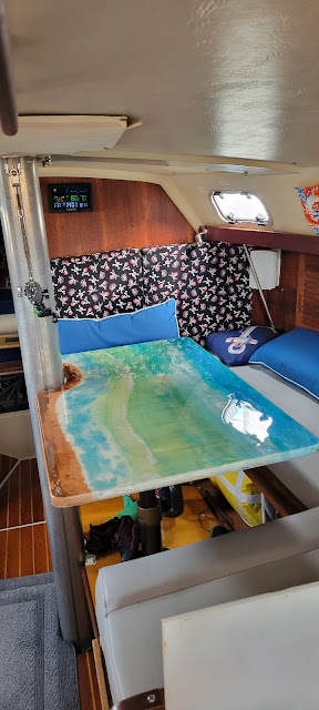
It has take over a year to complete our new Cabin Table on Eximius, but it's finally finished.

Here's a link to the early build articles Part 1 & Part II

Just in case you didn't know, we're in South Florida - and there's this thing 'Global Warming' happening. Well in Florida, that 'thing' is really obvious, it's warmer and the sea level is rising, we regularly have bigger floods and that's despite the grass suffering from a lack of rain.  The long and short of it is that it's been too warm to work with the resin -  until this week! November 2022 - the outside temperature was in the mid 60's. I quickly pulled the project out of storage and set to work. All it needed was a sander to remove a few tidbits from the surface and neaten up the edges, flood the surface with clear resin and use the heat gun to flatten where needed.  I followed that with a coat of grey outdoor paint on the underside.

Build complete.
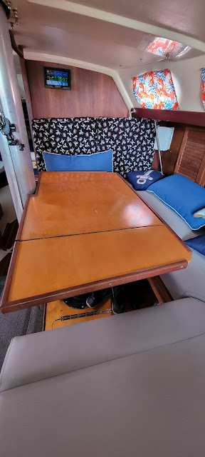
Before


After


Installing the table was easy.
The old table is connected to the central rising post with six screws and the post top is secured to the post with a single screw that forces a metal wedge against the post to keep the top steady.

A couple of minutes with my electric screwdriver and the top was off.

Laying the new table top on top of the post mount, I adjusted it's position so that the Starboard edge of the table was parallel to the edge of the seat. Then it was simply a case of screwing the table from below. Really easy.

Here's the result.  I would give myself about an 8 out of 10 on the production, but it's artistic, so it'll do just great.  Will probably make a fitted table cloth to cover it for when I do projects in the cabin.

Now to work on that forward bulkhead.

Another Project completed.


Sunday, November 6, 2022

A stitch in time

A sailors Stitch in time

Sailors know that wind can pop up really quickly and if your sails have a weakness then the wind will find it and find it quickly.

After our last trip, I noticed some broken stitching on the Genoa Sunbrella cover, about half way up the forestay. That's an 'in' for the wind to make a very expensive tear in the sail while out on the water. I have to fix that early.

So after recovering from the hectic party weekend with our friends from the HISC sailing club, we went back down to the boat and lowered the sail.

First I released the locking line that prevents the Furler from turning and thus prevents the sail from unfurling, then I released both of the Jib sheets, flaked out the Jib Halyard and released the furling line. Then went forward to pulled the sail down flaking it along the deck and on top of the inverted dinghy. It came down pretty smoothly. Then Peggy & I rolled it, not so easy, so that it would fit inside the sailbag.

We ( me ) had left the Aft whip secured to the Bimini when we left for the weekend party, it ripped out of the dock mount and needed repair. So we headed home with the sail stuffed into its bag and the Whip secured to the bed of our F150 ( towel wrapped around it where it touched the truck roof and secured with a few webbing straps.) Of course, Peggy wasn't so happy about us taking I95 back home with the 14' whip tied to the truck, but I persuaded her it would be just fine.

It was, we got home and I proceeded to plan the repair to the sail and the whip. 

Next morning I cleaned up the split end of the whip and mixed up a few ounces of resin. With a cheap paint brush I spread the resin into the open wounds of the whip and then closed it up using a half dozen old hose clamps. Then I setup my Sailrite Sewing machine and moved stuff around in my garage to handle the huge sail. While inspecting it to locate the area of stitching that needed resewing, I realized that the original Thread was no Tenera nor any other type of PTFE thread and that about 20% of the sewing on the Sunbrella cover had deteriorated. 

Meanwhile, Peggy called me from the laundry room that the washing machine was broken. Of course that's more important than the sail, I can do that anytime.

Figured out that the Washing Machine Pump was either not working at all or barely working, The tub was not emptying.  Off to google and the search for a fix. It's a common problem and Amazon has the pump for just $26. Google's YouTube had many videos showing how to replace the pump, not quite the same model as our machine but each of them pretty well had the same process. So I ordered the pump on A Prime.  Back to sewing.

Further inspection indicated that I should really restitch the entire Sunbrella cover, that's the full length of the Sails Leach ~44' and Foot ~ 13.5' That's a lot of stitching but my Sailrite machine is up to is, I have sewn bigger pieces. There's just going to be a lot of canvas laying around my garage as I try to feed it through the Sailrite Sewing Machine ( it's an LSZ-1 ) 

I spent a couple of hours sewing. The LSZ-1 handles sewing the sail with ease. The sail is pretty thick, there's a minimum of 1 layer of Dacron with One layer of Sunbrella which folder over the leach or the foot so that's a total of three layers. Then there are the overlaps in which case there are 6 layes - 2 of Dacron and 4 of Sunbrella. Sewing all of those was a breeze, each of the Sunbrella segments needed 3 rows of Zig-Zag stitching a line parallel to each edge of the Sunbrella and then a set of diagonal reinforcement lines about every eight feet or so.  The Leach required at least 280' and the Foot required 81' of PTFE Thread. I use Sailrite's Lifetime PTFE thread. It's difficult to get the tension right, but worth the effort.


Halfway through the sewing, Amazon delivered the Pump - that's the same day that I ordered it. First thing the next day the pump replacement floated up to the top of the Honey Do List. It only took a couple of hours to take the washing machine apart, replace the pump and put it all back together. Total Cost $28.76, that would probably have cost us at least an Arm if not an Arm and a Leg if we had a tech from Kenmore come out to fix it, and it would not have happened in just a couple of hours.

With the Washer out of the way, back to sewing. I was able to complete all of the restitching  of the Sunbrella and I looked over the stitching of the Sail itself. It looks like they did use a PTFE thread for sewing the Dacron, phew! because that is a lot of sewing to restitch that!

The final part of the sail repair was to inspect and restitch the webbing at the Head, Tack and Clew of the sail. Thankfully they all look very well sewn and not in need of restitching. However, the  thickness of the Sunbrella, the Dacron and the Webbing is just at the limit of my choice of machine needles. I'll call Sailrite in the morning to see which is the best size needle to use. I broke one today just as I was starting the backstitches at the end of the second piece of webbing on the Tack of the sail - I thought I would try it out, just too heavy for my needle.

Ok, Stitch in time is done, also fixed the Washing machine and the deck Whip, not bad for a couple of days work. 

Looks like a really wet week ahead of us, so we'll fold the sail up and put it back in it's bag till later when we can put it back on the boat. We're planning on heading out for a Thanksgiving Friendship Cruise with our sailing club and, of course, there's Thanksgiving on Thursday that week before the cruise. So we have most of a couple of weeks to get the boat back in order.

Till then.

Stay safe, and we'll see you on the water.


Thursday, October 20, 2022

Installing Orion DC-DC 12/12 18Amp TR Smart Charger

 Orion DC-DC 12/12 18Amp TR Smart Charger Installation

Here's a link to why I'm doing this, basically it's to charge our Start Battery.


Overview of the Orion Charger


The Install was pretty easy.

Mount the Orion on the bulkhead below the other Victron equipment

Drill a hole through the bulkhead for the wires from the Orion to the Start Battery

Make up an empty Fused wire for the +ve connection from the Orion to the Multiplus.

Make up the wire for the -ve connection from the Orion to the Multiplus

Inset the fuse and power up the Orion - Update the firmware and the program for AGM battery ( see note below ) then power it down ( remove the fuse. )

Makeup the Fused wire from the Orion output to the Start Battery +ve
Makeup the wire from the Orion output to the Start battery -ve.

Insert the Orion input fuse
Insert the fuse at the Start Battery
Monitor the Start Battery status on the VictronConnect App on my phone.


Notes:

  1. At present there is no way to view the Orion Smart DC/DC charger on the VRM. I did read where someone had installed a Smart Shunt into the -ve connection from the Start Battery to the Orion but have not figured out if it's worth it yet. There's also some issue as the Orion is an "Isolated" charger, but the Start Battery and the House Battery share a common ground. More research to figure that one out.
  2. The Preset Charging Profiles in the Orion do not appear to support AGM batteries except for Tubular batteries. However, Selecting any of the AGM type profiles and editing the profile switches to a User Defined Profile. We looked up the Duracell AGM SL178 charging profile and updated the charger's profile with those numbers.
  3. Although we cannot see the status of the Orion in the VRM we can see it via Bluetooth at the boat. Also, we can see this:


We did a test start of the engine today, 1st time using the new battery. What a delight, it virtually jumped into action. After 90 seconds the Tacho showed that the Alternator was running. We were on shore power and the VictronConnect app showed that the charger was in Bulk mode, a short while later, it dropped into Absorption and finally into Float.  Looks like I made the right decision.

See you on the water - We'll be taking the boat out tomorrow for the weekend.


Monday, October 17, 2022

Update on the Balmar MC 168 Install

 Update on the Balmar MC 618 Install

The install is complete.


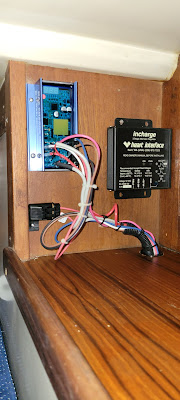
It's really difficult to keep the wires very tidy. But I was able to keep the fuse in an easy to access spot.

Note the Old external Regulator is re-mounted just forward of the new Balmar.

I emailed back and forth with PKYS about cutting the Battery and Alternator Temperature Sensor cables to improve the wire management. 

If you do cut these, it's a good idea to leave at least 2" of the Red and Black conductors beyond the outside sheathing, it makes inserting the Spade connectors onto the Balmar terminals. I had to recut my first attempt which kept them short and it was basically impossible to make the connections.

Having completed the install we had a few 'Pre-Flight' checks which are very clearly documented in the Balmar Manual.

I did note that the Engine Control Panel Tachometer drops to Zero during programming. That caused some concern as I had read on various forums that the Tach would not work when it was connected to the Balmar rather than directly to the Alternator. Once the Balmar saved any changes and dropped out of Programming mode, the Tach started reading correctly.

The only changes that I made in the default programming were:-
  1. Changed the Belt Load Management setting to 70%
  2. Set the Delayed Start from 1 second to 90 seconds.
The reason for #2 is to reduce the load on the Starter. This has a useful but unintended consequence. When the engine is started, the Balmar does not turn on for the 1st one and half minutes. The consequence is that the Tach does not display! But as soon as the Balmar passes it's 90 Delay start, then the Tach does start up. I find this useful as when the engine starts the Tach should read zero and 90 seconds later it should show the current RPM.

I wanted to set the delay to 2 minutes, but it takes forever to cycle through the programming steps and I just ran out of patience at 90 seconds ( which takes about 3 minutes.)  But 90 seconds is fine.

So, that completed the install and programming. We checked that the thru hull for the raw water was open and started the engine. Because of our dying starter battery, it took 3 tries to start the engine. See my last blog entry about that battery update.

At this point I'm very pleased with the install. We're taking the boat out for a multiday trip next weekend, that will involve at least 8 hoiurs of motoring and plenty of pull on the house battery capacity. 

Now, if the new Victron DC/DC 12/12 18Amp Smart Charger arrives before the weekend, I'll probably install it while we're on the boat :)

See you on the water.


Saturday, October 15, 2022

Charging the Start Battery

Charging our new Start Battery


Purchased a Duracell 12v AGM SL178 Battery to replace our 5.5 year old battery ( same make and model)

We found that our old battery was not being charged unless Shore Power was connected to the boat.

We had issues starting a few times recently and figured we should take the battery out of the equation.

The old battery will spend retirement in our Home Generator which has a long dead battery. Used the old Generator battery for the Core Charge recovery.


We need a reliable way to charge the start battery. Our House batteries ( 4 x Trojan 6v T105 Batteries in 2S2P configuration for 12v 450Ah.) and I decided to go for the Orion TR Smart 12 | 12  18 Isolated DC to DC Charger by Victron. 

Just adding to our Stable of Victron System equipment :)


The Orion can be used as either a Charger or as a Converter ( ie. stable DC output ) My plan is to use it to charge the Starter Battery from the House Battery. From everything I have read, it should only go into charge mode when the Input V ( House Battery V) is above a set limit ( set using the VictronConnect App ) and when the Starter Battery V is below a set limit ( again, set in the App )

So basically, this will mean that the charger will try to charge the start battery when the house battery voltage is above it's float value and if the Start battery is below it's Absorb value.

The House battery V goes up when it's being charged. ie. If the engine is running, the Multiplus is charging or if there is sufficient Solar to charge the House Battery. 

If that concept is incorrect, then there are other choices such as a manual switch to turn the Orion on, or the Engine Detection System override which would turn the charger on when the Alternator is running. 
Whichever method I end up using, it should involve keeping the existing Alternator to house Battery connection. I plan on upgrading our House Battery bank from Flooded Lead Acid to LiFePo4 batteries later this year/ early 2023. Their cost has dropped significantly in the past 5 months. Right now the Chin Batteries are looking good.

This diagram is modified version of the one in the Victron manual for the Orion.


This shows the Source ( Input ) supply being the House Battery and the Charged Battery being the Start Battery.

The Start battery is just a couple of feet away in a straight line, perhaps 6' around the bends from the other Victron Equipment. So I plan to install the Orion on the bulkhead adjacent to the Multiplus.

That will enable a short run of cable to the Positive Bus Bar and the Negative Bus Post, for the Input cables. The output will pass through the bulkhead adjacent to the Multiplus into the locker where the Start Battery is located.


I'll mount a 20Amp fuse on the +ve Bus Bar to the input of the Orion and a 20Amp fuse inline of the wire from the Orion to the Start Battery +ve.  The Start & House batteries share a common -ve. Victron don't make the 18Amp Orion in a Non-Isolated version and I understand that it's ok to join them, so there will be a wire from the -ve in and the -ve out to the -ve Bus post.

I'm curious to see if the Orion shows up in the Victron VRM if it does, then I should be able to view the charging history online. That would be cool too.

Ok, waiting on the arrival of the Orion, I have everything else. The max wire size for the unit is AWG6 
The Wiring calculator shows 14AWG but I'll use 10AWG.