Monday, March 28, 2022

St. Patrick's Day Cruise 2022


Sailing on St. Patrick's day

We try to get the boat out to celebrate St. Patrick's Day each year, it's just another reason to get the boat out and it's always a fun weekend.

Tides demanded that we leave the dock around 10am on Friday, the weather was cooperating so it looked like we could actually 'Sail'. This would be the first chance we have had to put the sails up on the Ocean since we installed the new Auto Pilot (Link to that post).

Nothing special about our trip down the New River except for a note about the FEC Railroad bridge. We lined up with other boats Upstream of the Seventh Avenue Bridge. There was a Catamaran and another power boat in front of us. As soon as 7th opened, the power boat went through but the Catamaran dawdled, that's not the way to go through a busy road bridge. Road traffic is halted and the other boats in line are waiting. Worse was the fact that they didn't know how to use the radio and their communications with the bridge tenders was unintelligible, the only way we knew of their boat name was because we were directly astern of them, it was not clear on the radio. We all passed 7th bridge and the boats behind us were closing up to us due to the slow boat ahead of us.  Now we hear that the FEC Railroad bridge is going down in Six minutes and the rate of progress of the Catamaran would put us behind the Railroad Bridge and that could mean hanging around for as much as an hour! I called the Catamaran  on the radio but they did not respond. I called again, no reply. I could see someone on the flybridge of the Catamaran but could not tell if he was at the helm of if the boat was being helmed from the cabin. There was a woman moving between the Flybridge and the cabin. What radio transmissions we heard from the Catamaran were made by a female voice, but still no responses to my calls. Finally I pulled alongside their Port side and gave them a taste of my Navy 'AHOY! which, if you have heard me, it's not easy to ignore. The guy at the flybridge turned to look my way. At that time I was far enough forward to see a tow ahead by the Railbridge. I sped up and moved over to the south side of the river to let the tow pass on my port side. The Catamaran was still not responding to any calls from either myself or from the Tow boats. Grrrrrr!

We made it pass the FEC Railroad Bridge and Andrews Avenue as well as 3rd Avenue bridge opened and stayed open while we all passed. Guess what! Still no clear radio comms from the Catamaran.

As we headed down to Sand Bar park, the intersection of the ICW and the New River, we turned at Marker #5 towards the 17th Street Causeway Bridge, the Catamaran was well  astern of us with Fenders still hanging from his Port Side Rail, I guessed the he was headed to the Lauderdale Marina just upstream from the 17th Causeway bridge. The bridge was open but due to close, there were no other sailboats astern of us except the Catamaran so I called the bridge and advised that we did not need the bridge to be open ( our mast clears the bridge when it's down, even at spring high tides, we have at least two feet clearance at the center of the bridge spans.

The 17th St. Bridge had been open quite a while, we heard the bridge tender call the 'Catamaran North of the bridge' asking if they intended to pass under the bridge, no reply, the tender called several times, again no reply. Finally, as the Catamaran was getting close to the bridge they replied to a desperate call from the bridge tender, we could still not make out the clear intentions of the folks on the Catamaran  and they still did not communicate clearly despite speaking English.

Well enough of that fiasco. We turned around the corner of Port Everglades entrance and headed out to the Ocean. We saw the Catamaran turn on the wrong side of the channel marker. They were probably shallow draft and not restricted by the depths, however, being out of the channel meant they were in the exclusion zone, normally a vessel straying into the exclusion zone would get a visit from the port police, but they looked pretty busy. They turned out towards the Ocean, still hanging fenders. 

Ok, we passed the 2nd Green Buoy of the entrance from Port Everglades and turned South East into wind and raised the Main ( we need to wash our main sail!) then, turning towards the North, we unfurled the Jib. We're sailing! 


And now the good news! 

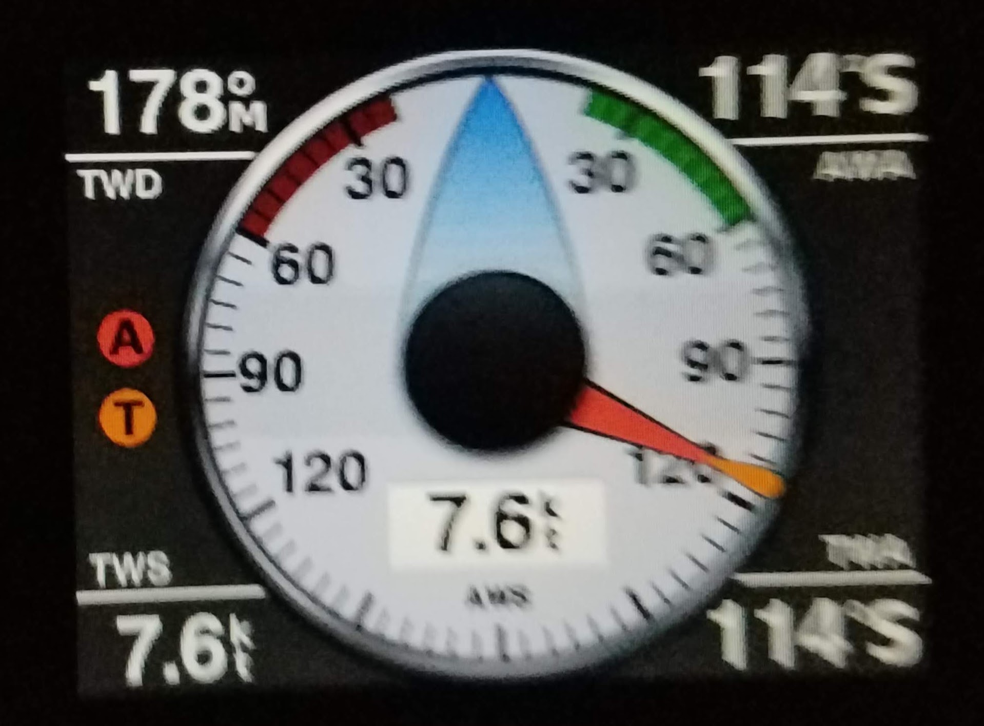
This (blurry) pic shows our Garmin Instrument displaying the wind data (at night) .
Note the big Black Dot in the center! It's Black, nothing there. We never thought about it being empty.

As mentioned, this was the first time we had taken the boat out on the Ocean since installing the new Auto Pilot.

We set the pilot to follow a track from Port Everglades up to Hillsboro Inlet.

After about 10 minutes, I just happened to notice this.


Look at the center of the display, it's showing Drift! 

Normally we would look at the Chart plotter and subtract the Water speed from the COG speed and calculate the Speed of the water.

Don't have to do that anymore, in fact, not only does the display now show the Drift rate but it also shows the drift direction.

l can only assume that the display was enabled when we added the Heading unit of the new Auto Pilot.

Sorry, it's a geeky thing, but this is very cool. I'm looking forward to seeing how it displays the data when we're in the Gulfstream.  WooHoo!


Ok, back to the sail. We sailed on Autopilot to within about a mile of the Hillsboro Inlet, turned into wind under power and lowered the sails. We motored into the inlet, the current was flowing hard and with the wind from the South East, it was wind over waves, that means - Bumpy! But we got into the inlet without any issues and then did a few doughnuts waiting for the bridge to open.

As we motored under the open Hillsboro Inlet Bridge, the Drift rate was 4.49knots on the nose (the triangular arrow in that center dot display shows the direction of the drift), that's a heavy flow and we were running the engine at just over 2,000 rpm. That was an exciting transit.

On the VHF Radio, we had heard Summer Wind call for the bridge before we were in range. Chris was taking the boat home from PlayBoy Marina where he had some bottom work done.  We motored easily up towards Hillsboro Blvd Bridge, as we neared it, there was a Tug pushing a barge and the bridges open on demand for commercial vessels (like tugs and tows). The Hillsboro Bridge tender called us and advised that we could follow the tug through if we wished. So we snuck behind the tug and followed it all the way up to Lake Boca. And Lake Boca was already crowded despite it being early Friday afternoon.

We anchored near the North West corner of the lake because it was too crowded on the North East corner. That put us closer to the ICW and a little to close to the other anchored vessels (they looked like permanent residents) so we dropped a 6-1 rode thinking that we would move in the evening when the power boats all headed home. 
They didn't. So we had to wait till the morning to move to the North East Corner, but when we did we had a prime anchoring position.

As the day wore on, Saturday turned into a great day to be on the Lake with a bunch of other club members and their boats.  Mike Megarity on Spruce Goose, Mike Miceli on Loony-Poons, Chris and Kelli Whitlock on Summer Wind, Barry Simmons & Jamie Remacle on Lady Grey, Tom Garvey and Norma Glanz on Ohana,  Mike & Brenda Duvall on Imagine, Jeff & Judy Keiser on Affection, Pierre & Osa Holstein on Sea View, Sea Dragon, Blythe Spirit, Bob & Joyce Tiger on Diversion, Eduardo & Eva Rabadan on Cookie Monster, Bill & Collen Stolberg on Duet, And of course, us on Eximius.

Of course, there were probably a couple of hundred other boats, large and small, it looked like there were a lot of people ready to enjoy the weekend.

One of our best stories was about a small power boat that tried to anchor about 20' off of our Stbd side. Sure it was too close, but we have learned to deal with that at Lake Boca. The number of boats in the lake at a weekend with good weather is crazy! So, this power boat dropped his anchor. Peggy & I were sat in our cockpit just enjoying the view, it was obvious that the power boat had not put out enough rode and he kept dragging and moving further North, basically along our stbd side. Then he pulled in some of the anchor line, it didn't help, so he threw out another anchor off his stbd side, now his boat swung at an angle to his first anchor and the boat was still drifting. I spoke to him (he was close enough to our boat to hold a conversation. ) and asked how much of his main anchor line he had out, he replied that he had 20' feet out at first but he was dragging so he pulled some in. Duh!  I tried to tell him that in 9 feet of water and a bow roller about 3' above the waterline, meant that he should have 5 x 12' or  60' of rode.
He explained that he had done a boaters safety course and that he should have 50' of anchor line for a 20' boat. I was about to give up and just watch him drift further to the North where there were other boats anchored (and not dragging). His female guest/wife on the Bow said something to him and the next thing we know is that he has pulled up both anchors and was heading out of  the lake and up towards Palmetto Park Bridge. Good plan!

At 6pm, Chris stopped by our boat to give us a ride over to the Hosts on Loony Poons, There were quite a few folks already aboard and soon that number increase enough to flow over to Summer Wind.

After a few drinks, the food was attacked, there were a couple of serious Shepherds Pies and plenty of other food, there always is at our club events.

Jokes, Limericks, Songs and a good time by all, by dark we headed back to our boats, the boat stories flowed along with our drinks, we even covered some club business. 

During the early morning we were awakened by the noise of an anchor chain being pulled up or lowered. Quickly out on deck, we could see the host boats raft up were moving South, deliberately. They were being quite well behaved which was surprising because it was dark, hand signals didn't work, and we could only hear 'Forward!' or 'Reverse' and 'Neutral' which we guessed were the commands to whoever was at the helms of the three boats. Come the morning the host boats dinghy'd over to our raft up and explained what had happened. You probably guessed, some of the boats were too close and when the current changed around, that turned into a gentle bump or more. Well done the skippers and crew of those three boats, and one being a catamaran. 

Sunday morning breakfast and it was then time to separate from the other two boats in our raftup and head homeward. For Cookie Monster, that was a move of about 150' for us it was a motor all the way down to Sunrise Bay, we reached every bridge on time, didn't have to wait for any of them, so it was a reasonably quick trip down the ditch.

Of course, Sunrise bay was packed with Party Boats, but we found a decent spot to anchor and guessed that most of the Party boats would leave the bay by 6pm. They did, and we had a quiet night at anchor.

Monday morning we left Sunrise Bay and headed down the ICW towards 17th Street Causeway Bridge and then a sharp turn Starboard down 15th Street for a Pump out, it's the second time we have used that facility, it's great, the Pump is not particularly strong, but it gets the job done.

Once pumped out, we headed out of the canal and turned to Port and back towards the New River turn off at Sand Bar Park. We had a minor incident as we held between 3rd Avenue Bridge and Andrews Avenue bridge. There was a Tow in front of us which meant there was not a lot of space between the two bridges. In retrospect, I should have turned the boat downstream which would have put us with the current on the boat and the wind on the bow. With strong forces dictating our movements, at one point we touched a fender of a boat on our Stbd side. No harm done except to my pride. We probably held station for about 10 to 15 minutes, that's stressful. If we had  a full keel it would have been virtually impossible unless we had a Bow Thurster - we don't. Once past Andrews Avenue Bridge, I turned the boat to face the current and wind and we easily held station while waiting for the FEC Railroad bridge to open.  Then it was turn again and head up river to the fork and the up the North Fork of the New River to our dock.

Back at the dock, Peggy made a snack for us as unloaded the boat and rinsed it down, especially the anchor chain, it had a lot of use this weekend.

See you on the water soon.


Saturday, March 12, 2022

Our Battery Charger Failed

Zantrex Freedom 20 Inverter/Charger failed


We noticed that our House Batteries were not charging and dived into the power management system to find out what's wrong.

After a lot of diagnostic testing, we concluded that it was the Freedom 20 Charger that had failed. It's 18 years old and was a DIY installation back in 2003. We have extensive notes on the system, all of the Manuals and diagrams that have been expanded to over the years with hand written notes.

Going to the web, we found (Peggy spent hours working on this part) that the Freedom 20 has a couple of fuses inside, but they only control the Echo Charger it charges the Start Battery.
There are a number of relays (at least 3) in the unit and it could well be one of those, but they are soldered into the circuit boards and I'm more likely to damage that trying to replace the relay than fix it. Lastly there's the possibility of a failed circuit board. I could find an old one but that feels like fixing an old car that has a bunch of other things waiting to fail. Finally, there's the fact that the Freedom 20 cannot be used to charge LifePo4 Batteries. Not that I'm planning on replacing the batteries, yet, but .... Santa is due in just 9 months!

So, I'm going to replace the energy management system.  

One thing I did like about the Zantrex System is the integration and the control. I'm a bit geekish, so those things are both  cool and valued.

The decision after a month of research is to go with a Victron System. 

Just two weeks after we realized that the Charger had failed permanently, I was invited to attend a Victron North America Training Tour in Davie Florida on Monday Feb 14th (yes Valentines Day - I had to play that one very carefully). The seminar was excellent! A full day of exposure to the variety of systems that Victron has available and, of particular interest, how they integrate with the boat systems and communicate outside of the boat if desired (oh yea!)

Trying to keep the Boat Bucks under control, I decided on the following equipment:

Victron Multiplus 3000VA
12v 120 Amp Inverter Charger

Initially, I was going with the Victron Energy MultiPlus 2000VA 12-Volt Pure Sine Wave Inverter 80 amp Battery Charger, Compact.
However, while at e-marine, they showed me the Multiplus 3000VA 12 Volte 120 amp charger, the size and shape are a lot closer to the old Freedom 20, and it was less than $200  more. 

This has a 3000VA (3KW) Inverter and a 12v  120 amp battery charger, it also has a 12v  4 amp trickle charger which follows the charge profile of the main battery charger.

It will talk to a Cerbo GX so that means there's a lot of control options.

The Inverter will also provide power assist if the load exceeds the set shore power. ie. if the Shore power max is set to be 10amps then if the load exceeds 10amps, the inverter will assist, the amount of assist is also managed.
Lastly, it can act as a UPS, if the shore power fails, it can switch over to Inverter mode in a few milli seconds.

Victron Cerbo GX Network Hub
Victron Energy Cerbo GX, Panels and System Monitoring.
Basically, this device is data central. All of the victron devices that can communicate on the VE-Bus can plug into this device, then with either a PC plugged into it or a wifi device connected to a wifi network, the data can be viewed and the settings changed.
It has a Micro SD Card Slot so that it will store up to 120 days of system history  - WooHoo!


Victron GX Touch 50 Display/Control panel

Victron Energy GX Touch 50, Panels and System Monitoring (Waterproof)

This display will cover the hole in the existing panel but will provide a lot more info than our Zantrex Link 2000R control panel for the Freedom 20 Inverter/Charger (not working)


Victron Energy VE.Bus Smart Dongle (Bluetooth) (Although I may not need this as the new Multiplus may have both Blue Tooth and Ve Bus connections to the Cerbo GX, I'll confirm that shortly.
I'm now certain that this part is not needed.


Victron Smart Shunt 500Amp

Victron Energy SmartShunt 500 amp Battery Monitor (Bluetooth)
This will allow monitoring of the battery charge status and communicates with the Victron Connect App and the Cerbo GX


That equipment will integrate with the existing Victron products that I installed a couple of years ago.

Victron MPPT Smart Solar Charge Controller

Victron Energy SmartSolar MPPT 100V 20 amp 12-24-Volt Solar Charge Controller (Bluetooth)

This unit provides the best Solar Power form from our Solar Panels. The plan is to upgrade two of the three panels as they are low power panels and waste a lot of the available real estate for PV power.

I may have to upgrade this charge controller


Victron Smart Battery Sense

Victron Energy Smart Battery Sense Long Range (up to 10m)

This unit has a self adheasive backing and is wired to the Battery +ve & -ve terminal 

(The negative terminal will be moved to the load side of the new Victron Smart Shunt)


Then there's the geeky stuff...

Victron GPS Module

This is a Victron GPS module.
Why do I want this? 
Well, if I link the system to the cloud, the data will include the GPS location. We can do all sorts of good research with that.
Such as 'Where were we when we had a slump in Solar Power' etc. or Where's the boat right now? 


Victron GX- LTE-4g GSM Cellular Modem


This is the Victron GX-LTE-4G GSM Cellular Modem for Victron devices.

The GPS module connects to this device, it also will take a Sim Card.
This unit connects to the Cerbo GX network hub and gives it access to all of the data stored and live from all of the devices in the system.

Victron has a VRM Portal. All of the data will be uploaded on a set schedule.

With the data online, we and the tech support team can review the current state of the system as well as historical conditions. The VRM portal also allows for update of the settings remotely.

The GX Touch panel dimensions are bigger than the cut out hole for the existing Heart Interface control panel, so that should easy installation of the control panel.

The Multiplus dimensions are close to the Freedom 20 is located, I may have to trim the shelf under the Nav Table, but only by a few inches.

The location and length of the +ve and -ve wires to the Freedom 20 will not fit directly to the Multiplus, so I'll have to replace those two wires. The 110v In and 110v Out wires to the Freedom may reach the Multiplus so I may not have to replace those two wires also, but will be ready to replace them.

Then there's this:
That Red Cable is attached to the Chassis Bonding Lug on the Freedom 20! GRRRRRR!

Marine Electricians would throw a hissy fit over using a Red Cable for a Ground Bonding /Wire!

So that cable will have to be replaced also. It will be a Green Cable and I'll check the size (AWG) as it's a safety route for unexpected current to flow.


Ok, now for the schematic. This is a dynamic diagram (it's created in Google Drive ) but I'll make a copy of it to cater for any changes needed during the installation.
Power Management Schematic (note the date)


Update: 02/21/2022 - The Multiplus 3000 Inverter Charger has a 4amp trickle charge for the starting battery - but that would only charge the Start Battery when AC power is applied! So I think I may need to add a Victron Smart Orion DC-DC Charger to the system. That will allow a more controlled recharge of the Start Battery. Of course, this is all questionable. The draw on the Start Battery is high load but short duration and it could be that the trickle charger would suffice for our Start Battery profile, but by adding the Orion, it begs the question - Do I need it?  I don't have a record of the Start Battery model, I know it's a Duracell AGM but with the model # I can lookup the charging parameters. The Orion addition also paves the way for a house battery upgrade to LifePo4. The Multiplus 3000 dictates the maximum Ah capacity of the House Batteries - the daily energy consumption dictates the desired maximum Ah capacity. 

Ok, time to close this part of the Upgrade. Next part will cover the supply of the parts and the removal of the existing system.

The removal involves:
  • Turn off the Solar Power
  • Disconnect the House Battery +ve 
  • Remove the Zantrex Freedom 20 Inverter Charger
  • Remove the Link 2000R control unit & electronic pack.
  • Remove the external regulator (not used right now) and the cables to the Link 2000R
  • Run a temporary wire for the Bilge Pump to the House Battery (don't want the pump to be out of action during this job.)
  • Remove the existing shunt.
Should get all of that done on Day 1. All of the heavy duty power cables (for both the DC system and the AC system) are available locally so if any are needed we can drive to a supplier on the way home, there are several suppliers within an hour's drive of the boat.

Day 2 - Physically mount the GX Touch 50, the Multiplus 3000, Cerbo GX, GX-LTE-4G GSM Cellular Modem, GPS unit and the Victron Smart Shunt 500 (which should fit in place of the existing Shunt).

Day 3 - make all of the inter device cable connections and determine any replacement power cables (DC or AC) get them locally.

Day 4 - Connect the Multiplus to the system (DC Cables & AC Cables)

Day 5 - Connect the system to the batteries, then turn on the Solar Power and connect Laptop to the system to review initial settings.


Saturday, March 5, 2022

Temperature Monitoring Hot and Cold

Monitoring our Boat's Fridge/Freezer and Hot Water tanks.

Our Fridge/Freezer has an adjustable Thermostat but no temperature indicator and there's no temperature indication for the Hot Water Tank. The fridge/freezer temp is important, we don't want our frozen food (think Klondike Bars) to defrost and don't want to waste fresh water running it until hot water (if there is any) to find out if it's hot enough for a shower.


Solution: Install a Dual Temperature display.

This one is from Amazon, $15

"WIDE TEMP RANGE - Temperature Range -58 ℉ ~ +257℉(Fahrenheit); Temperature measurement accuracy: ±1℉ (±0.1℉ when temperature within -9.9~99.9F). It can be not only used in water but also used to measure the air temperature. But the water temperature will be more accurate than that of air."

It's a small display, Size: 48*29*22mm. The probe wires are just 3' long, but some of the reviewers modified them to extend further.


Plan is to mount one Probe on the side of the Freezer box in the Fridge/Freezer and the other inside the thermal jacket of the Hot water tank.

As often is the case, determining where to locate the display is the challenge. The preference is somewhere that is visible without having to move anything or crawl/stoop down to some awkward position, but also away from any moisture, so not by the counter top.

I'll drill a small hole in the side of the Fridge walls and lead the wire for the probe outside of the insulation. The hot water probe will simply slide between the internal hot water tank and the fiber insulation between the tank (round) and the outer casing (rectangular). I think that the whole tank will need to be removed in order to insert the probe. There is a small area by each of the pipe attachments that I could possibly use, I'll make the decision when I get down to the boat and start on this project.


The unit has 3 connections on the back, one for each probe, the 3rd is for the power supply.

It draws about 8-9mAmps at 4v approximately 0.32Watts.

With a voltage range of 4v to 28v, the voltage drop over the power cables should not be an issue, I'll run power cables from Connection to the Compressor with an inline fuse. I'll use 16awg cable as that is the minimum size recommended by the ABYC.

This does mean that the Hot Water temperature will only be displayed if the Fridge/Freezer is powered on, but if we're on the boat and thinking about taking a shower, then the fridge/freezer will definitely be turned  on.


Back to the issue of where to mount the Display. There's a wooden panel that covers the midships water tank vent pipe on the forward side of the Galley  storage shelf. It would be easy to remove that panel, mount the display, connect the probes and power supply, replace the panel and we should be in business.

(The red arrow points to the planned display location)


Got down to the boat today and viewed the Probe location options.
Seems like the probe for the Hot Water Tank will fit by one of the 4 cutouts in the outer case of the Hot water tank. I should be able to slip a probe in touching the surface of the tank and use a couple of cable ties to secure the wire to the hose. I'll add a piece of tubing to insulate the wire and then feed it into the loom that goes up behind the sink area.


Just another fun piece of technology, an easy project. 


It turned out removing that wooden panel was easy, not sure if it is original boat woodwork though.

Easy cut out, drilled each corner than used a Fret Saw to cut out between them. 

Fits like a glove, the side 'Buckles' actually reach to the back of the panel, so it snaps in very securely.

Now to make the extension leads for the Power supply. I made the decision to get the supply from the Refrigeration Unit just forward of the Midships Water tank on the Starboard side. That's about 10'.

Next job is to extend the power cables and the cables on one of the Probes as it is too short to reach the Hot water Tank.

I'll do that at the boat. The wires will be Butt Connected and waterproofed with Sealed Heat Shrink tubing. I have not seen the power connection at the Fridge Compressor unit, need to take photos of that. 
The Fridge compressor unit is located just forward of the Midships water tank, getting to it will require some boat yoga effort.


Display Test

Here's the display setup on my workbench. I have an old 12v Power adapter (6amps) that I use to test gear at home.

The hot probe is in a cup of hot water, the cold probe in is air, the cold temp is actually my garage temperature, I'm wearing a sweatshirt, this is South Florida on January 29th 2022 !!
The temperature change reading is quite slow, it takes a while to register the increase although it does display the change about every 1 seconds. 


After sanding the panel and a couple of coats of varnish, it looks a whole lot better.

Our long term plans include lightening up the cabin by refinishing the wooden surfaces, there's a lot of wood, some of it will get painted. 
The ideas is that if the surface is smoother they will require cleaning less often due to mold growth which really is a problem here in South Florida.

I'm pretty sure this wood is Teak, it's much prettier without the darker varnish and years of exposure, most of the boat woodwork is that original dark finish, lightening up to match this finish will make a big difference.


This is the 'varnish' that I have used on the Companionway Steps which look great, it looks great on this display panel too.

Minwax Water Based Polycrylic Clear Satin


Day 1 of the installation.

Saturday January 5th 2022
The panel fit just fine, that was easy :) 
First wire to run was for the Hot Water Probe, I cut the Probe cable, it has two black wires, one was printed with white text. I connected the Red side of Black and Red Tinned Copper wire 16awg with Butt joints and then fed the other end of the twin wires along an existing loom under the sink over to the Stbd side below the Fridge/Freezer and up where the Water Fill Hose and the Tank Vent pipes ran and out to where the display is fitted. That took about an hour and a half and a lot of boat yoga.

To connect the Cold probe, I'm going to drill from the fridge forward wall, through the inch or two of insulation and then through the stringer which is outboard of the galley forward bulkhead. The probe wire is only 30inches long, so I'll probably have to extend it the same method as the hot probe.

The power to the Refrigeration Unit is connected via a screw down wire clamps, not really suited to adding two additional wires, so I'm rethinking the power supply. There's a Lighting power cable just above the Display housing, so I'll use that for the power supply just using a pair of electric cable connectors.

Looks like it will take a couple more hours to complete.

Moving ahead. I snipped one of the Probe cables and used Butt joints to connect it to a length of Twin 18AWG wire. Fed the wire from the Hot water tank end along the existing loom to the Stbd side just aft of the midships water tank, then up using a fish tape to through the existing wire holes just forward of the galley fridge/freezer and then aft to the Display unit. That took about an hour but looks neat and is supported every 6-8" 

Next I drilled a hole in the forward bulkhead of the fridge freezer near the top and as far outboard as I could get my cordless drill, it was only about 3" from the inside of the fridge  freezer to the forward bulkhead (Hull Rib). I fed the wire my from the inside the fridge and was surprised that it went straight through first time! Sweet. Then I followed the existing loom which included the probe wire from the hot tank, up to the display unit.

Last part is to hook up the power. The lighting circuit in that area has a lot of connections, sadly, some that I have added. So I'm going to rework all of those and put them to a small terminal block mounted on the upper side of the cabinets. Those wires provide power to the LED light over the aft salon table seat, the two LED lights over the Galley and the Fan over the galley. My plan is to move all of the Fans to a separate circuit (we have 4 Fans and a 5th to install in the aft berth). Meanwhile, I'll just connect the Temperature Display unit to the Cabin light circuit. I have much bigger fish to fry. (stay tuned for an upcoming intro to that upgrade)


Ok. Here's a pic of the probe mount inside of the Fridge.

That pic shows the metal temperature probe secured to the outside of the freezer box using a cable tie hold down clip that is mounted on the separation ferrules. It's really difficult to see from looking down into the fridge/freezer but it's very secure. I added a strain relieving cable tie to secure the wire to that ferrule too.

That method alleviated the need to drill a mounting hole in the surface of the fridge/freezer box itself.


All done!

The final wiring was pretty straight forward, it is connected to the Lighting circuit.

Right now the Cabin temp is 81º F so the hot water tank is actually cooler! 

The Fridge/Freezer (blue) temperature is set for max cooling, and the display varies from 31.3 (as shown) to 8ºF when the Compressor is running.

We'll see how the hot water temp shows when we next run the engine.

Ok, sign off on this one.

Oh, the lighter finish of the woodwork is appreciated by the Admiral. It's a winner.


See you on the water (we are right now, rafted up with 4 other boats from the HISC in Lake Boca)