Tuesday, July 26, 2022

Refinishing the Non-Skid on deck

Refinishing the Non-skid deck surface.

The Non-skid on deck of Eximius is crying to get refinished and it's time.

Sometimes, things become a lot easier when I take the time to write out the details of the job, and that's why I'm writing this post. Of course, it might help others and that's a benefit. if you would rather read about some of our cruising antics then skip this one, but if you need to refinish your boat deck, it may be worth the read.

Port side Anchor Locker Cover

Stbd midships deck


After discussing the project with the guys from Catalina Yachts, I concluded that the following is a process I can handle.

As the non-skid is a diamond embossed surface and the masking tape will not affix so neatly, I anticipate that it will be easier to refinish the areas outside of the Flat Grey and Grey Non-Skid first and then refinish the Grey flat and Non-skid areas second.

Get the materials.

  • 3M 233+ High Performance Masking Tape
  • 3M 2090 Scotch Blue Painter's Tape
  • TotalBoat Dewaxer & Surface Prep.
  • Awlgrip Polyester Urethane Topcoat Base Quart
  • Awlgrip Awlcat #3 Topcoat Brush Converter
  • Awlgrip Flattening agent
  • Scotch Green Pad Scouring pads.
  • Paper towels - lots of them.
The epoxy paints:


The 545 Epoxy Primer will be used where necessary. I could only find it in 1 gallon cans and coverage should require about 1.5 Quarts, I'm sure I'll find a use for it elsewhere on the boat.


Refinishing the regular (flat) areas of the deck.

This is probably the difficult part of this project. I'm leaving the hardware on the deck in place but making sure that it's well masked off and any chips or hairline cracks repaired as necessary. 


Step 2: Prep the Deck

The non-skid on the deck could be original, it's a diamond pattern however, the finish is badly worn due to frequent foot traffic, in some areas there appears to be roller marks. ie. Swaths of the surface color about the width of a paint roller are obvious. In other areas, the surface is actually worn away - particularly, the tops of the Anchor Locker Covers. On those covers, the underlying fiberglass strands can be seen. The good news is that the covers are solid fiberglass so there's no risk of damage below the fiberglass. The rest of the deck is in great shape, it's just that the non-skid surface is worn away.

I spoke (online chat) with guys from Jamestowndistributors.com and they were very helpful, they even had a guy that had done a technical course with Alwgrip, so my confidence in their help was high. Matthew sent me a link to the document that covers the Alwgrip application process if very granular details. (link to manual

The preparation sounds pretty simple but the manual indicates that there's a few tests that should be done to ensure really good adhesion. (It's on Page 17), so I'll be doing that test on the worst part of the deck. I expect the job will require priming, hence the addition of the Primer to the list of materials.

  • Mask off the area to be processed.
  • scrub the area to be painted with the Scotch Green Pad Scouring Pads, it's a lot of work. 
  • Apply Alwgrip Primer.
  • Apply 2 coats of Alwgrip Paint with flattening agent ( prevents glossy finish)
The good news is that the deck can be processed in clearly defined areas, so it does not have to be completed in a single step. I'll break it down into 13 areas. 6 Port Side, 6 Stbd Side and the Center panel above the cabin access cover. The 6 areas are listed below. Each area is demarked with a plain finish strip between the Non-skid areas. All of the Non-skid areas have edges of the same color but plain finish.
    1. Anchor Locker Cover
    2. Foredeck 
    3. Mid deck 
    4. Aft Deck 
    5. Cabin Top
Ok, so all the products are in and I have the plan, but have to wait till it's cooler, so plan is to do this sometime after September. So stay tuned :)

So, the weather seems to be cooling down to below the mid 90ºF and I should be able to start this project. Plan is to bring half of the anchor locker cover home and practice in the Garage - why risk overheating at the boat, a week or two and it should be much cooler.
The paint has sat in the garage for quite a while, so I'll have to give it all a really good shake up.

I called Jamestown Distributors and they confirmed that the products should be ok even after two years but are only warranted for 12 months.

I brought the Port side Anchor Locker Lid home and followed the plan: Came out great. Issues? Yes, the brushes can only be used once. So I purchased half a dozen 2" brushes after the 1st natural bristle ( twice the price ) was useless after one coat of primer.

Oh! Always needing paint stirrers, I found if I cut the metal and bristles off of the dead brushes, they handles make really good paint stirrers for quart cans! 

I did buy some can 'Spouts' but they really didn't fit the quart cans very well so I used painters tape to create a pour spout that was really easy to clean up.

Priming and painting took 5 coats and mixing small quantities really doesn't work very well but when I work on the main deck areas then I expect the mixed quantity to be more cost effective.


This photo shows the two Anchor Locker lids reinstalled after 2 coats of primer and 3 coats of top coat.

The difference is remarkable! There is no indication of the damaged surface whereas the deck area immediately aft of the lids clearly show the damage.

Click on the image to zoom in.

Update on the areas to be worked on.
Each side has 6 defined areas that should be able to be processed using about the same quantity of primer and topcoat as I used for the anchor locker lids - that's because I could not mix a very small amount and get the ratios correct and the lid undersides were also refinished.  

I have a quart of primer, a quart of primer converter so that's a half gallon of primer mix.
Also a quart of topcoat base and a pint of topcoat converter, a quart of topcoat flattening agent. That's over a half gallon of top coat.

I also have a quart of brush reducer which is mixed at about 20% for both the primer and topcoat.

So I'm pretty confident that I'll have enough to finish the job.

I have a bunch of sewing jobs coming up over the next few weeks so the deck finish will be on hold till at least the 2nd week of December. ( Boat is going into the yard for a bottom paint -- etc. the first week of December. )


Sunday, July 24, 2022

3/8" & 1/2" Template Marking Device

 Making a Template Follower

I do quite a bit of Sewing: Biminis, Dodgers, Screen covers, Tank Covers, lots of Cushions and a plenty more. One consistent issue is marking the covering material to be 1/2" greater than the template for the Foam on a cushion.  

If I place the foam or a cardboard cutout, as a template on the material and run a sharpie or chalk pen around the foam ( or cardboard cutout ) then the Fabric is the same shape as the template, but I need to add a 1/2" seam allowance. If the edges of the template are straight lines, then it's easy to just use a ruler. If the template has a curve, then I can use a bendy rule but it's awkward.

I cam up with the idea of making a Template Follower

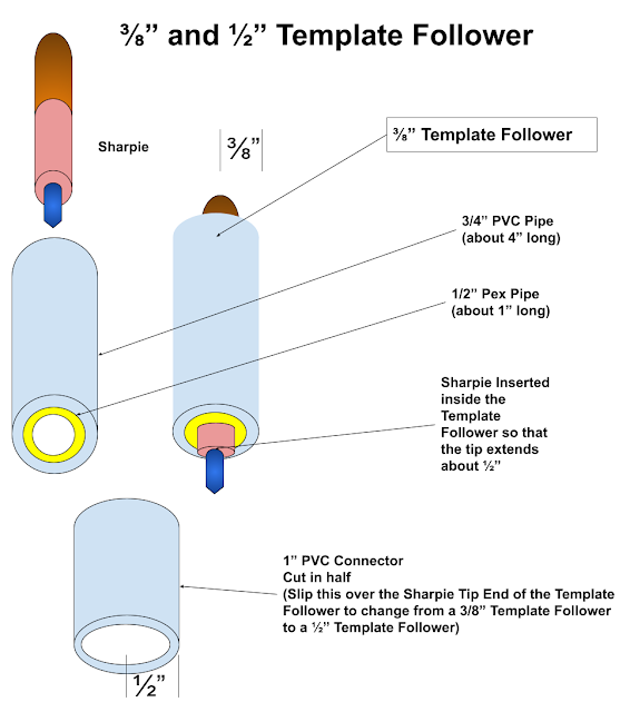
The concept is simple. Insert a Sharpie pen inside of a tube, then hold the tube vertically against the template (Foam or cardboard cutout) laying on the material to mark up. Then move the Template Follower around the edge of the template, the tip of the Sharpie marks the material.

The Follower is easily made: Just cut a piece of 1/2" Pex piping about 1" long ( it actually needs to be long enough to allow the Sharpie to be inserted into one end such that the tip of the Sharpie is protruding from the other end of the Pex by at least 1/8" of an inch. Then that piece of Pex is pushed inside of a piece of 1/" PVC Piping about 4" long such that the PEX protrudes about 1/8" from the PVC Piping.

That makes a 3/8" Template Follower. A 1/2" PVC pipe connector will slip (tightly) over the 1/2" piping, so I simply cut a 1/2" PVC Piping Connector in half across it's diameter and with that slipped over the 1/2" PVC piping, it converts to a 1/2" Template Follower.


Thursday, July 14, 2022

Victron GX Touch 50 Menu

Victron GX Touch 50 Menu


This Post is based on my Victron System, a system with other components will be somewhat different.

The new Victron Power Management System that I recently installed on Eximius has an extensive system management menu on the GX Touch 50 Display/Control panel. It has well over 300 Menu options and navigating through the menu in order to find a particular setting or info display page can take hours! I built the spreadsheet included in this post to assist me in locating any setting or info included in the Menu System.


Note. My MultiPlus 12/3000/120-50 120V is named 'Eximius MP3000


I hope you find this useful, please leave any suggestions on improvements in the Comments.

Here's the Menu Structure

Notes:
If an item in the spreadsheet is White Text on a black Background, that reflects the top item of the current Menu. In the real menu, that line also may show the current status of the display. 

My display includes the Location Icon, the Connection Type and Bars and the current time. 


Try searching for a Menu item using your browser's 'Find' option 
( Chrome = Ctrl+F )
eg. If you're looking for the 'Reboot' menu item, Press Ctrl+F
Then type in 'Reboot' (no quotes) and the word 'Reboot will be highlighted wherever it appears.


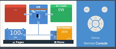
I have found this info really useful as I navigate around our new system on our Sailboat. The sheet was constructed by navigating each of the Menu item as displayed in the VRM Remote Console. The actual display on the boat is almost identical but functionally it's the same.

Thanks for taking the time to read this.  If you would like to have your own copy of the spreadsheet so that you can modify it yourself to match your system components, just ask in the comments and I'll send you a link to share the Google Sheets file.

See you on the water!

Paul

Tuesday, July 12, 2022

ATN Ascenders

Using ATN Acenders

I have climbed Eximius' mast quite a few times, the most recent was this past week when I decided to replace the rechargeable battery in our Garmin gWind Wireless mast head transducer. 
The outcome of that trip up the stick was that it's not the battery so I need to see if the transducer can be repaired or replace it with a Wired gWind Transducer. 

That means I have to do at least two more trips up the mast more likely three.

The method I use to climb the mast is using the following setup.
  1. Secure the end of the Spinnaker Halyard to the base of the mast and cinch up on the other end at the cleat on the Mast.
  2. Secure the end of the Spare Halyard in the same fashion.
  3. Detach the Main Halyard from the Mainsail and secure that end to the Bosun's Chair.
  4. Tie a Prusik Knot using a 1/4" line onto the Spinnaker Halyard
  5. Tie another Prusik Knot with another 1/4" line onto the Spare Halyard
  6. Don my Safety Harness & Tether, attach the free end of the Tether to a Carabiner on the Main Haylard end.
  7. Tie the ends of one Prusik Knot line to the Bosun's Chair D rings
  8. Tie the ends of the other Prusik Knot Line to the Foot straps Loop.
With the Chair and safety harness setup, I then position the Prusik Knot from the Chair to a point as high as I can reach and sit down in the chair.
Next I hook the foot strap loops one over each foot and move the prusik knot to about 6" below the other Knot.

Now I adjust the attachments of the Prusik knot lines to the chair and foot strap loops until I can sit in the chair and then stand up in the loops.

Ok, now ready to climb the mast. Peggy will tail the Main Halyard on the winch as I climb the mast.

Climbing the mast is a task, the biggest part is shifting those Prusik knots one after the other. Each time I may have to partially release the loop of the Prusik knot in order to allow them to slide up their Halyard. That means that the maximum distance between the knots is determined not by my ability to lift my feet in order to raise the knot, but the distance that I can still release the Prusik knot's loop.
That way, the distance I can move up the Halyard with each move is restricted by the use of Prusik knots.
And that probably the reason that many climbers use Ascenders, quicker, easier and less exhauting.

Searching the web for a pair of Ascenders, I found that ATN, which is a Company is just down the road from where we keep the boat ( ok, about 15 mins away ) has them. So I stopped by to check out their 'Ascenders' 

I meat Etienne, very nice guy, very busy but graciously took the time to show me his Ascenders and explain their use and features.  
His store is a hive of activity, they make Spinnaker Sleeves ,Mast Climbers, Catamaran Trampolines, Storm Sails, Spinnaker 'Tackers' and much more. His team where all busy and he had a significant amount of jobs in progress. 

Etienne showed me how to attach the Ascenders to a line and explained how he has his own Bosun's chair system which incudes the Ascenders.  

I had watched the YouTube video of his that shows how to climb a mast single handed using his system. It's impressive, however, I don't think I'll go up the mast unassisted. I'd hate to have any kind of issue up the mast and have to come down to sort it out. Much easier to have a deck assistant that can send up something when needed via a messenger line.

So I purchased a pair of the Ascenders, took them back to the boat and checked out that I had memorized the process that Etienne demonstrated. I did, it's pretty straight forward.

The next day, Peggy came to the boat with me as I had to go up the mast to retrieve the non-functional Wireless Wind Transducer.

Getting up the mast was actually more difficult then using the Prusik knots, but I figured it out it was my fault. I had set the lower end of the fixed halyard to the forward cleat. That meant that I had nothing to hold onto when climbing, but more importantly, I had the Ascender to which my foot strap was attached too high, that meant that I had to reach up really high when raising the Ascender that was on my chair. As a result, my feet would swing out really far and it would take a lot of physical effort to move the upper ascender.  I confirmed this later when back on the deck. I'll attach the Foot loop so that it's Ascender is about waist high when standing on the deck and the Chair Ascender about face height when standing on the deck. That way I can sit down and easily raise my feet, taking the weight off of the foot loop ascender and making it easy to just slide up the Halyard. No need to release the prusik knot, the Ascender slide up easily when there's no weight on it.

Ok, so next time, I'll adjust the Ascender positions before attaching the Chair and the Foot loops to them.

Despite my error, I was able to climb the mast and it was a whole lot easier when I was above the Radar Reflector and able to steady myself with my feet on the Mast. But best of all was the fact that I could now easily stand with my head and shoulders well above the Masthead. As I have to do quite a bit of work next week when the new Wind Transducer and the new VHF Antenna Cable arrive and I have to go up the mast again. Oh the joys of boat work.

I do plan on adding to my Bosun's Chair a secondary harness that eliminates the chair seat slipping up my butt when I stand in the Foot loops. Not a modification to the chair itself, just a simple pair of adjustable leg straps to keep my butt firmly in the seat.

Ok, so a big shout out to ATN, I feel very confident in the Ascenders, there's no chance of them detaching from the halyard and there's no need for a fixed line with a simple bitter end as the Ascenders clip onto the bight of the Halyard.

Next time up the mast, I'll try to get Peggy to take some pics as I prepare for the climb.

See you on the water - assuming I fix the Wind Transducer and that we don't have any of the 'H' type of weather events. 


Tuesday, June 28, 2022

Fixing the gWind Transducer

Fixing the gWind Transducer


Our gWind, Wireless Transducer failed during our trip to Biscayne Bay over Memorial day weekend, I guessed that it was the Battery and ordered a replacement online. Yesterday ( June 27th 2022) it was time to replace the battery.

I took my phone with me when I climbed the mast, but sadly, it was in a pocket that I could not get to when wearing my harness and in the Bosun's chair. So the pics are some that Peggy took down on the dock.

I'm pretty sure that the Main Halyard sheave at the top of the mast needs to be replaced as neither Peggy nor Mike,  club buddy that came down to help out and provide additional safety, could pull me up using the winch! So I did my usual practice of climbing the mast: Using a pair of prusik knots on two separate halyards, one tied to the Bosun's chair and safety harness  the other tied to the foot straps. Using them I can sit in the chair, raise my feet and then raise the foot strap prusik knot as high as it will go (about a one foot stretch). Then I stand up in the foot straps, taking the weight off of the chair, raise it's prusik knot, sit down and repeat. If I move the seat knot up by close to 1' each pass, then it takes about 40 moves to climb the mast. In reality, it takes a lot more, probably eighty moves as some of them are only a few inches while trying to maneuver around the shrouds and especially the last couple of feet.

Once I had gotten to where the foot strap prusik knot it as high up the halyard as it can go, that's about 8" from the top of the mast, then I can stand up and my shoulders are above the top of the mast and I can reach pretty well everything up there.


This time the plan was to climb the mast and replace the gWind Transducer's battery. The transducer is held in place by a clever bracket and nut system. Simply pull off the clip that stops the nut from unscrewing, unscrew the nut, pull the whole transducer arm forwards and slightly upwards. It takes less than an minute to release the Transducer.

With the Transducer on my lap in the chair, I used a #1 Philips head screwdriver to undo the small screw that holds the battery cover in place. It was easy to lift off the cover, unplug the old battery, plug in the new one and replace the cover. The insides of the Transducer looked pristine so no apparent water ingress which is a problem with the heavy rains that we get here in South Florida. 

I did note that the Solar Panel on the top side of the Transducer was 100% opaque, completely white! I'm guessing that means that the Transducer is not going to charge the battery. We have had wind data on our Nav system on every night trip, so the battery is just there to cover the times when there's no solar power and normally, rechargeable batteries are at least partially charged when new.

Less than a minute to reinstall the Transducer and call down to the team ( Mike & Peggy ) down below and ask them to test the system.

Sadly, that didn't go well :( 

With the Nav instruments powered up, the display lit up showing that it was powered but the data came on but only for a few moments. It showed wind angle info ( True Wind and Apparent wind Directions) but no wind speed, after a few moments the data disappeared. If we reset the Nav instruments, then it would pretty much repeat that scenario. 

I've been in the Bosun's chair I was ready to get back to deck level. Going down was a lot easier, I Mike & Peggy used the winch to haul the main halyard and take all of the weight and I eased the two prusik knots, then they eased the winch and as I moved down, I just moved the prusik knots with me.

They stopped lowering me when my feet were able to get on the spreaders. From there I freed the line for the lazy jacks that was stuck between the sheave and cheeks of the block attached the mast above the spreads. I need to replace that block ('blocks' as there is one on each side of the mast )but it's free right now so we can adjust the lazy jacks.

So, my thoughts.   If the solar power is zero, then the battery will run down within a day or so, but if there's any solar power getting into the battery, then it should charge up within a day or too also.

If it's not a Solar/Battery issue, then it's the gWind and looking at the reviews on the web, that's a strong likely hood. Under normal conditions, it's not unusual for the wind data to just disappear for a few minutes and it normally comes back if we reboot the system which we only try if the data does not return within about 5 minutes.

Options:
  • Check it today and all may be well.
  • Replace the Transducer with another gWind Wireless = $750+tax
  • Replace the Transducer with a wired gWind = $650 
It's nuts that the wireless Transducer is so much more than the wired unit, as the wired unit has so much more in the Kit 

Using the wired unit brings me back to why we used the Wireless model originally: Running a new wire up the mast is a significant job.

Other things to consider.
If I do end up replacing the Transducer, and if I go the Wired route, then I might as well replace the VHF antenna coaxial at the same time, the existing coax has a much higher power loss than a decent cable and that would improve our VHF communication range both for Transmission and Reception.

Ok, first things first. Go down to the boat and check out the status.

A day later: 

The system is still not delivering data from the Transducer.

I spent a good while on a text chat session with Garmin this morning. From that chat I conclude the following:

#1 If the transducer is the older generation then I'm out of luck and will have to purchase a new item that's $750 plus tax.

#2 If the transducer is a new generation, then I should be able to get an out of warranty exchange, that's $350

#3 If I replace the Wireless Transducer with a Wired unit, I should be able to connect it to the GND 10 and disconnect the no longer needed WSI Box (the Wireless Receiver).

The Wired Transducer will cost about $650.

I'm leaning towards the Wired Transducer and replacing the VHF Coax at the same time.

Time to get busy and earn some boat bucks.

See you on the water, even if I don't know the wind speed & direction.


Reusing Heat Exchanger Zinc Cap

Reusing Heat Exchanger Zinc Cap


<<< Zinc ---- Cap >>>
The Zinc Anode for the Universal M25-XP heat exchanger is in two parts. The Zinc and the Cap.

There must not be any insulation between the zinc and the Cap nor between the Cap and the body of the Heat Exchanger. The whole idea is to allow the zinc to corrode rather than the body or tubes of the heat Exchanger.


The problem is that the screw thread of the Zinc corrodes with the metal (Brass?) of the Cap. As the Zinc corrodes during it's stay inside of the Heat Exchanger, the zinc is washed away in the flow of the salt water that passes through the Heat Exchanger. So when it's time for the zinc to be replaced, it's in a pretty weak state and often breaks off when trying to remove it from the Cap.  <<<< Just like this.

I know, change it more often. Will do!

I tried drilling the zinc out, gave up pretty quick.

Then I tried Barnacle Buster !!!! Wow!

As it happens, I have a spare Zinc Cap from a previous change out, so I'm seeing what happens.


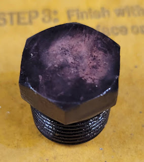
Here's what it looks like after 48 hours
The remnants of the zinc have gone and the threads are clean.

It looks kinda grotty, but in fact is is extremely clear of the debris from the old zinc


The Cap's end gives a clue.

By the way, I used a pair of stainless steel tweezers to pick the Cap out of the Barnacle Buster, the tips of the tweezers have that similar black color now.


This pic shows the Cap after literally 2 minutes of wire brushing using a brass wire brush.

This is after rinsing and drying.

I have no issues with using this as the Cap during a future heat exchanger zinc change.

The stores sell the zincs either with or without the Caps, I have a couple of spare zincs without the caps.

Now I have 2 usable Caps.


Love making progress, even on the little things.

See you on the Water


Saturday, June 25, 2022

Securing the Alternator on our M25-XP

Securing the Alternator on our M25-XP Engine

The alternator on our Diesel Engine has moved about due to vibration (hey, it's a 3 pot Diesel) and has broken the support arm twice.

I purchased a new 10mm x 100 mm bolt and a Nylock nut to replace the old one just in case some of the slack in the Alternator mounting was due to a worn bolt.

It also occurred to me that the mounting bracket spacer might not be suitable for the Alternator ( which we replaced a few years ago). My calipers were not accurate enough to measure the gap between the Spacer and the Alternator Ear (I think that's what they call it), it would really require a Micrometer and I don't have one ( YET! ) 


On Amazon I found some 10mm internal diameter shims, 10 each of 0.1mm, 0.2mm, 0.3mm and 0.5mm and purchased those.

By trial and error process, I figured that the existing spacer between the Alternator support brackets and the Alternator Ear had a 1.2mm gap.

Using two 0.5mm shims and one 0.2mm shim the alternator 

With those 3 shims in place, I was amazed at how batter the alternator was supported by the brackets.

It took about 10 minutes to fiddle the shims on to bolt after it passed through the foremost support bracket, then get the Spacer onto the bolt, there is obviously almost no gap now, and finally the bolt into the aftmost support bracket. With the Nylock in place but barely tight, the alternator felt rock solid in the mounting.  


After adjusting the drive belt tension and securing all 3 of the bolts that hold the alternator in place, it feels total as one with the engine. Solid! 

With everything tightened up, Peggy started the engine. Not a hint of a squeal when she shifted the rpm up to cruising speed and no movement of the alternator. 

I'm hoping we have cured that issue of vibrating alternator and subsequent breakage of the tension support arm.

I hear the waves beating against the bow! See you on the Water.